MIMA Pack Whack and rebalancing the battery | 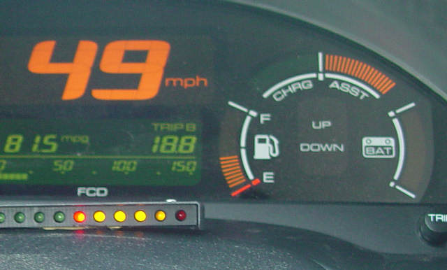 | | | Whack the pack to erase the cell memory and fix recals |
The MIMA pack whack could be a huge new advantage to owning MIMA for the many people struggling with limited capacity battery packs due to recalibration's.
The pack can also be balanced with the grid charger described below.
*****DANGER, THE BATTERY AND THIS PROPOSED CHARGER CAN ELECTRICUTE YOU, DO NOT ATTEMPT THIS IF YOU DO NOT HAVE THE PROPER TRAINING*****************
As many of you know, I have been using MIMA on my pack since 80K, and as I approach 180K, the pack still runs fully from top to bottom, on each cycle. Since I do not have recal's, it is something that I was not able to examine. On my trip to Hybridfest, I flew out to MI,to ride out with Ed Zandee,a very savvy auto technician who owns his own service center in Grand Rapids. Ed purchased a used 2000 Insight with 130K on the clock.Like many older Insights, he was getting a typical recal whenever his pack reached 5-6 bars from the bottom. Ed Installed a MIMA system the day before we drove the 350 miles to Madison. I drove some of the way, and got to experience recals first hand for the first time. Ed and I started to experiment and analyze what was happening. We noticed that the recal point seemed to move up the scale one bar as the pack temp increased.We also found that full regen could be applied with MIMA, even though the SOC guage was showing full and limiting the standard IMA regen.
I have since confirmed that my pack will stop MIMA charging near the top bar, so it is synchronized with the SOC display.
Most of us with MIMA will stop regen when the SOC is at the top, since we fear overcharging.
This is where we do the PackWhack.
Just let the ABC keep charging until it is limited, even though the SOC is at max.
Drain it down till no assist is available, and you have given it a stop to stop full charge.
On the way back, we again took turns driving,We decided to push past the SOC top end and using MIMA we continued to freely charge, for quite some time while the SOC was pegged at the top. A good pack will stop excepting charge from MIMA when full,even if the MIMA system request it, so this was a new experience for me.
We decided to keep jambing charge into the pack to see if it would eventually start limiting, and eventually it did, but only after putting in the approximate equivalent of charging to about 6 more bars.
We then switched on PIMA, and started running a lot of assist. We were drawing full assist for several minutes, before the SOC finally began to drop, and it dropped smoothly to the recal point, and then recalled as normal, but this time, even with no bars of SOC, we were able to draw the full 100 A of assist for several minutes as the photo above shows, until the assist finally became limited. We ran the pack through the cycle another time, with the same results.
We got back to Ed's place, feeling that the pack was outputting a lot more capacity than before.
The real surprise came the next day, when Ed brought me back to Detroit for my flight home.
The recals were gone. We cycled the pack several times, and the SOC ran from the top,right to the bottom.
Ed will do some more test runs with his Honda factory scan tool and get us more information. Making some assumptions which still need to be tested, my read of this experiment is that the SOC limits that stop normal IMA action at both ends are different that the BCM top and bottom limits which are based on actual voltage measurements on both ends.
When a pack starts having limited capacity issues due to the memory effect, the SOC in normal IMA mode will stop regen when the guage is at the top,even though the pack is really not charged fully. The MIMA forced charge is limited instead by the BCM when it determines that the battery voltage has reached the max. So this MIMA PackWhack as Ed and I began to call it, allows the pack to be fully charged past the SOC gauge limited point that the standard IMA is limited by, and is only stopped when fully charged, therefore doing the equivalent of a equalization charge on a lead acid based pack.
I suggest that any of the MIMA owners that have recals give this a try. Just stay in an ABC forced charge, or manually do regen until the charge is limited even though the SOC bars are full. Then do assist with PIMA or MIMA until it starts to be limited on the bottom end.
Do several of these cycles, then see what happens with your recals the next day.
Of course you are doing this at your own risk, as it will take some time to see if this effect is temporary.
This blog will be where we will put the results of further testing of this experimental procedure.
All recals are not the same, so this procedure is for the standard regular recal at a specific SOC that seems to be the most common.
A long time MIMA user from CT drove up on DEC 13 2008. He was getting repeated P1568 codes.(Battery Module Individual Voltage problem) If the car was allowed to sit, it would sometimes clear and things would work normally for a while. This was happening on a daily basis, sometimes more than once. We looked at all of the pin plug MIMA connections and found that they were solid and all were firmly plugged in.Wiggling the harness did not cause any issues.
Since the code would indicate that a subpack was showing a voltage match problem compared to the rest,I suggested that he try the pack whack on the way home. He did a full MIMA induced charge until limiting kicked in, then did a discharge to the bottom, then started driving normally.
He has put over 300 miles on the car since then with no further codes.The pack whack can definitely help
many problem battery packs, and for all of the MIMA owners, it is very simple to do.
This blog starts at the page bottom.
|
How do I test the sticks to determine which I need to be replacedOk, I have answered this question so many times, that I feel it needs to be in print.
The lack of detail is intentional, as this should not be attempted by anyone that cannot understand what I have written.
The IMA big switch needs to be off for all but the last full balancing grid charge.
*************************************************
This pack can kill you, so don't attempt this if you are not qualified working on HV equipment.
**************************************************
After you pull the pack,you will need to open both ends so you can remove the sticks.
Carefully remove all the screws on each side.
The relay side has rubber plugs that need to be removed before you can get to the connection screws.
On the orange end connector boards, the the little screws are for the PTC strips.
Be gentle, and don't bend the small PTC tabs any more than required to get the plates off.
Once the screws and end plates are off, you can pull out the sticks.
On a couple of the sticks you will see the temperature sensor wires.
Beware, if you try to pull out these sticks, you will break the thermistors, so slide the sticks toward the wires until you can cut them loose from the tape that is holding them, then pull out the stick.
Record where in the pack they were the temp sensors are located, as you will put them back when you re assemble the pack.
You need to test each stick to see how many AH it can produce, and how well it holds a charge over time.
RC hobby shops have special charger/conditioners, that do a nice job of automatically cycling sticks of NIMH cells
Many to choose from, and I can't make a suggestion so you need to do your homework.
After you cycle each stick 3 times and record the Ah on each discharge, give the stick a number, and record the AH, time and date of the last discharge, then one more charge. Put the cell on a room temp shelf, and one week later you will discharge the cell and record the AH.
During the cycling, you will likely see the AH increasing on each cycle, this is normal for NIMH cells, and is why no serious RC electric modeler will be without one of these charger/cyclers.
After 3 cycles, you will likely have reached the max AH recovery.
You should see a range of values.The smaller the range the better the pack.
The best could be 5-6AH, and the worse could be less than 2AH.
At this point, anything below 4 AH may want to be replaced, but if the whole pack is at 4AH, you can still use it, as long as all the sticks are in the same range. One stick that is at 2 AH,in a pack of 4AH cells will likely have problems, but a pack of well matched 4AH cells and an occasional grid charge , and you may be ok for years.
The match between the sticks is more important than the actual AH, to a point.Once the Ah gets below 3AH, the pack will not provide much assist before hitting empty.
My numbers are not meant to be taken literally, only as a guide.
3 cycles is all that you should need to do on each stick to get to the best capacity.
After a week of sitting in the charged condition, do a measured discharge to see how much the AH is different from the last discharge the day of the Cycling.
A good stick may be within 5-10% of the last discharge after cycling. A bad stick, with high self discharge will be much lower in capacity, The matching of sticks requires that the % of residual charge after a week delay should be similar on all sticks.The best sticks will have the smallest % difference from the last charge on the day of cycling.
Repair:
Get a replacement pack and test all those sticks the same way, and after it is all done, you pick the best matched and highest AH sticks to put in your pack.
reconnect the sticks making sure to put them in with the correct polarity, and when attaching the orange end plates, make sure to carefully feed the PTC wires through the slots and reconnect securelt with the small screws. The big 10MM bolts on each stick end need to be tight to assure good connections.
When the pack is all together.
At this point, turn on the switch, and give the pack good balancing charge to bring all of the subpacks to full.
Turn off the switch, and put the pack back inthe car, and you will be good to go.
You should see your IMA problems solved.
While you have the pack out of the car, you may want to install a charger harness, so the pack can be rebalanced by one of my chargers.
Any sticks that drop more than 30% after a week are on the edge as far as being good for a long term replacement, but a pack of sticks with similar capacity and self discharge can be kept operational with a weekly balancing charge of the whole pack.
Good luck
Mike
(Posted 10/5/2011 by mikey) |
Replacement for 1 Watt LED | 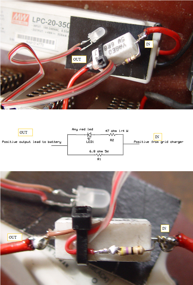 | | | One Watt LED replacement |
Several people have found it difficult to get the 1W led that I specified on the grid charger schematics as a current indicator.
The 1 W led shown above works pretty well, but I have blown out two of them with the surge current that happens for a split second when the charger is first connected. This simple circuit uses a 6.8 ohm resistor to develop about 2.3V@ 350ma.
The 47 ohm resistor controls the current through the LED.
The total cost will be less than the 1Wled, it will not get hot so no heatsink is requied,and it will not blow the led with the initial current burst when connecting the charger
(Posted 9/25/2010 by mikey) |
Looking better on the second cycle | 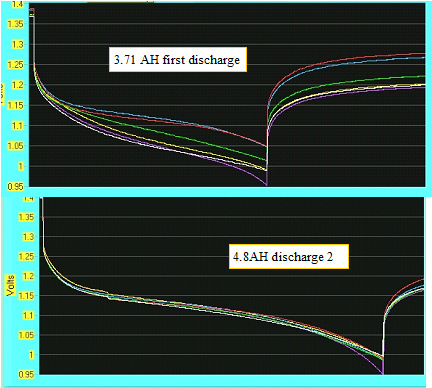 | | | looking better on the discharge |
Ran a second charge discharge cycle on the #9 stick, and things look better, cells tracking much better than on the first run. Will run a couple more cycles and see what we see.
(Posted 3/6/2010 by mikey) |
Not really rebalanced just changed???? | 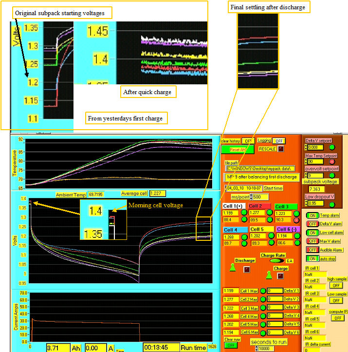 | | | Not really rebalanced???? |
Talk about counter intuitive,here is what happened this morning. Note that the cell 1 and cell 6 were initially (as removed from my old pack)the highest voltage, with 5,3,4,and 2 at progressively lower voltages. At the end of the fast charge they remained in that voltage order. The photo of the long rebalance showed all the cells really close.
The charging went several hours past the last photos,and I found that the cells that were at the lowest initial voltage had risen to the exact reverse order and they stayed in that order even during the during the discharge.
What does it mean?
Based on further cycles, the highest initial voltage may be the weaker cells?
If the weaker cells hold 4 Ah, and the better ones hold 6, the better ones will never get fully charged, and the weaker ones will get overcharged.
once the better cells are fully charged, in a topping operation, they will allow a fuller cycle for all, therefore erasing some of the weaker cells memory effect reduced capacity, and bringing them all into better balance.
(Posted 3/5/2010 by mikey) |
Rebalancing? | 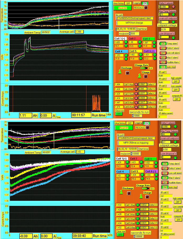 | | | could this be proof of rebalancing? |
I had to go out for a long trip, so I set up one of the 350ma CC supplies and put it across subpack #9.
9.6 hours later, it looks from the trace that the cells that were unbalanced worked their way up to the same level as the better cells. After 3 hours, just before I left for the trip that trend upwards had just begun to happen.
I will let it soak for a few more hours, and tomorrow after a night of settling we will see if the cells truly rebalanced.
Notice on the top photo how unbalanced the initial cell voltages were when the charge first started. Some unbalance was still evident after the initial quick charge.
The bottom ragged trace was because of the switching regulator noise in the CC supply getting superimposed on the cell voltage, and the fact that instead of the half second per sample, I lowered it to one sample every 10 seconds, so the file would not be too large.
I disconnected the current probe during the 350maCC charge to save the 9V battery in the probe,as we know it was 350ma.
(Posted 3/4/2010 by mikey) |
Subpacks 1-8 | 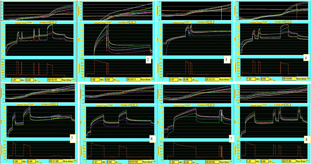 | | | First 8 subpacks |
Zeroing in on a screen layout that works best for me.
Started the pack testing with a quick first charge to see what my subpacks look like, and so far, they look pretty shakey.
The bottom trace shows when the charge current switch takes place, and you can see the voltage rise on the cells. Lots of good information, we just need to understand what it means.
I think #8 looks the best so far.
Will trace the rest tomorrow.
(Posted 3/4/2010 by mikey) |
Getting better signals | 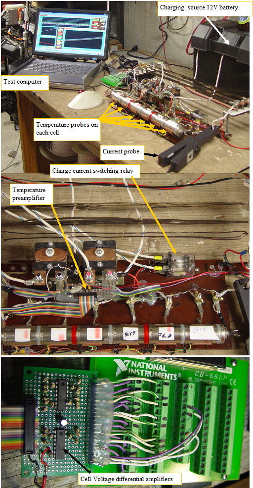 | | | Next tester upgrades |
To get cleaner traces, I built pre amplifiers for both the temperature and cell voltage signals, as well as adding a low current charge control nichrome resistor.
Now I can charge at 35A and switch automatically to 6A for a gentler finishing charge. The new temp sensors sit in direct contact with the bottom of each battery case at the bottom of the copper clip.The probes respond near instantly as I thermally couple them to the cells with a small dab of silicone thermal grease
(Posted 2/21/2010 by mikey) |
more tuning of the controller/ Datalogger | 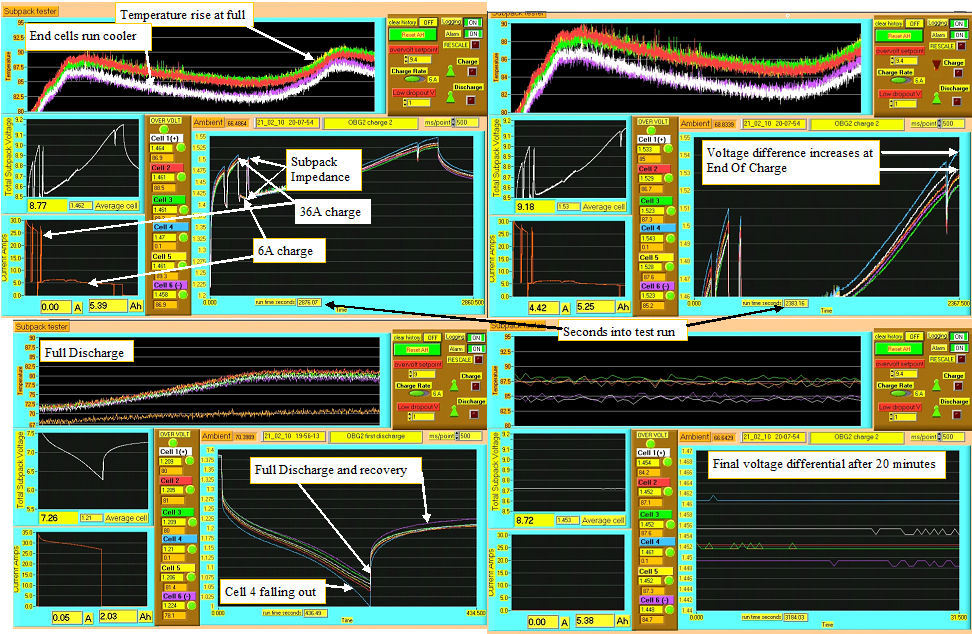 | | | next subpacks |
Traced another subpack with the next generation of the tester.The photo shows 4 screen grabs at different times in the cycle.
Still would like more signal from the temp probes, but this should be good enough. The cell and temp preamplifiers bump up the signal so we have better digital resolution for smoother dataloging.
I will try reading the cell resistance when switching from 36A charge to 6A charge.
(Posted 2/21/2010 by mikey) |
Refining the tester | 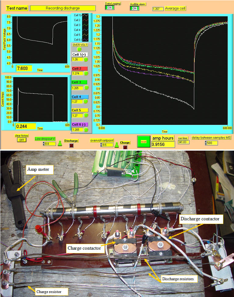 | | | Refining the tool |
Worked like hell to get three MIMA systems ready to ship, only to miss the PO by 5 minutes, so I came back home and worked more on the hardware and software for my subpack tester.
I like the overlaid graphs, and the whole event on one log, so one can see the trends and differences between cells during charging and discharging.
I lightened up the load to about 65A instead of the 100, as this subpack was toast when I started with it. The overlaid graphs clearly how the condition of the cells. The white trace is the problem cell 1, and as we view more of these traces, we should be able to run a couple of cycles and simply view the graphs to see what shape the subpack is in, and what cells are having problems.
The charger is one of my big Trojan AGM31 batteries, and I use one of the nichrome resistors to produce a nice comfortable 30A of charge. I will record a charge cycle tomorrow, and hope to install a preamplifier board to bump up the signals levels a bit.
The card only has a 12 bit a/d converter that is looking at +-10V full scale, which yields .0048V per bit. Just barely enough, and this is the major cause of the jitter in the trace. If I amplify the voltage for each cell X4, the traces will be much better to look at,with an effective resolution /bit of .0012.
(Posted 2/9/2010 by mikey) |
Subpack tested first high current run | 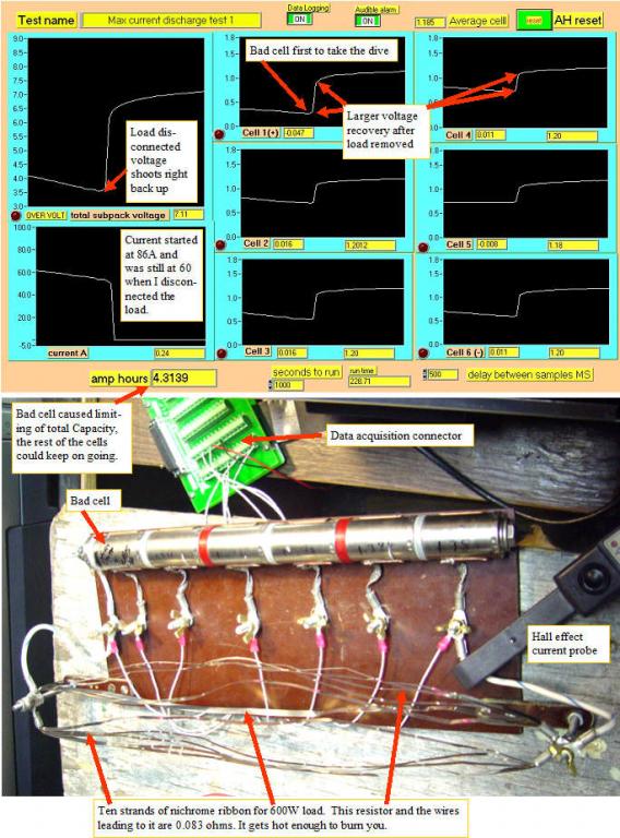 | | | First high current discharge test |
Same stick, two days after the last test, after charging at 350maCC for a day and a half.
The bad cell still showed s .05V lower voltage that the others at the start of the test. The load got the current up to about 86 amps. The 10 strands of Nichrome ribbon,got up to about 250 degrees. If I want to hit 100A, I need another 3-4 strands. The "zapped" cell gave up at over 4AH, and was just about ready to reverse, or maybe it did reverse for a fraction of a second, as it will reverse if I reconnect the load.
The drop off was so fast that I could not get the hot brass wing nut "switch" turned off in time.
I am charging that cell first, and will charge the whole subpack tomorrow.
Need to zap the cell harder, maybe the arc welder?
Cell 1 was noticably hotter than the rest, but they were hot. Next time I will add a log of the 6 cell temperatures
(Posted 2/4/2010 by mikey) |
Subpack tester first test | 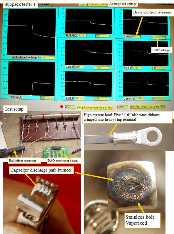 | | | First test and analysis |
I got out my working notebook with it's data acquisition system, and wrote a quick labview program to monitor, display, and write to a file what is happening on each cell. I will add AH computations tomorrow.
The high current connections worked reliably through out the test, with only a slight rise in the #10 wire temperature to show for it. The discharge test at 35A, showed an initial voltage difference on cell #1 (the shorted one)of about .08V it lagged the other cells by about that amount for most of the test.
I got a long 1-3 minute discharge at @35A,beforethere was a rapid drop off of cell #1 voltage, just as the others started to accelerate their downward plunge. It was so fast I couldn't get my cameras turned on fast enough to shoot it.
So the shorted cell performed at say 80% the capacity of the others, and had a lower fully charged voltage than the others at full charge.
I can't help but think that I need a better zapper.
I took some photos of the big alligator clip and Stainless steel bolt head that was my capacitor zapper switch.The amount of plasma damage suggest that we may have lost a good deal of the energy in the contacts.
Now that I made a spotwelder that can put out 10,000A, controllable length pulses, I need to try this again.
We must remember that these cells are designed to produce 100A, so we need to hit it with many times that if we hope to vaporize the dendrites.
(Posted 2/2/2010 by mikey) |
failure mode #1 Shorted Cell and the cell Zapper fix? | 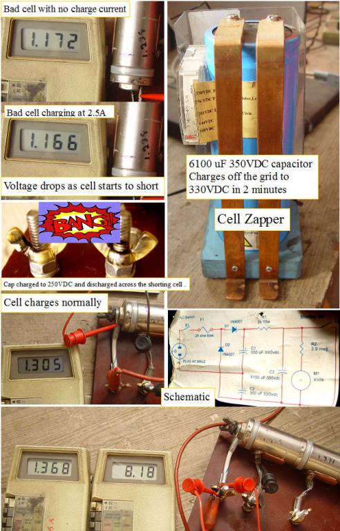 | | | Cell Zapper test #1 |
In years past I have used a capacitor to zap shorted NI CAD batteries back to life.
I ran some test on the first stick from Ron's shorted cell pile of subpacks.
Cell #1 (most positive) was lower voltage than than the others an hour after the stick was taken off the overnight 350MA charge.
I put a 3 A charge across the low cell, and instead of raising in voltage, it dropped, as it began to short.
I dug out the stored energy demo from the hybrid car class. We use it to show why you need to turn off the switch and wait for the capacitors to discharge before touching anything. The 6100uF cap has copper buss bars, and a voltage doubler circuit to get 350VDC from the 120V AC line.
I charged the cap to ~100V and discharged it right on the heavy brass wingnuts.After A look at the voltage under charge, and still shorting. Another zap this time @ 250VDC and the short is gone, and then for good luck, I charged the cap to 350VDC and zapped the whole subpack.
You can see that each discharge generates a divot in the brass nut and capacitor buss bars. Wear ear and eye protection as it sounds like an M80 going off, and molten metal can spray out if you don't make the contact fast and hard. Lots of the capacitor energy is not making it to the cell, and is making explosive metal plasma.
After confirming that the cell voltage was rising at about the same rate as the other cells, I put the whole subpack on a 3A charge until the cells were at 90%, then finished with a 350MA for several hours. Final cell to cell voltage while under charge was within 0.05V
Will see what happens overnight and do more testing tomorrow.
(Posted 1/31/2010 by mikey) |
What is wrong with the subpacks? | 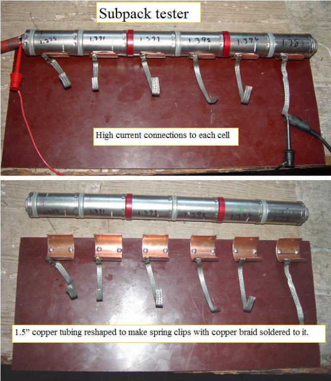 | | | tapping the subpacks at the cell level |
After hearing about battery pack failures for the last ten years, I decided it was time to actually see what goes wrong with the subpacks, and see if there is a way to restore some of them. Ron from Hybrid Battery repair gave me a couple of dozen subpacks that had failed for various reasons, so that gives me some examples of the failure modes.
I made some rugged hard copper spring clips from a piece of 1.5" copper tubing. The tube was cut in half, then reformed over a 1" steel rod in a vice. This worked perfectly. The copper clips had a heavy copper braid soldered to each, so I can charge or discharge with high current at the cell level, or zap the cells individually with a capacitor discharge.
First subpack was totally discharged by shorting each cell until they were totally depleted. This is safe when it is done on a cell by cell basis, as the cells cannot reverse.
I put the subpack on a 350ma charge and I will let it charge until it reaches a stable max voltage.
Then a high current discharge while watching the voltages. I hope to finally determine the possible failure modes and see if anything can be done to fix them?
(Posted 1/30/2010 by mikey) |
universal dual stage grid charger | 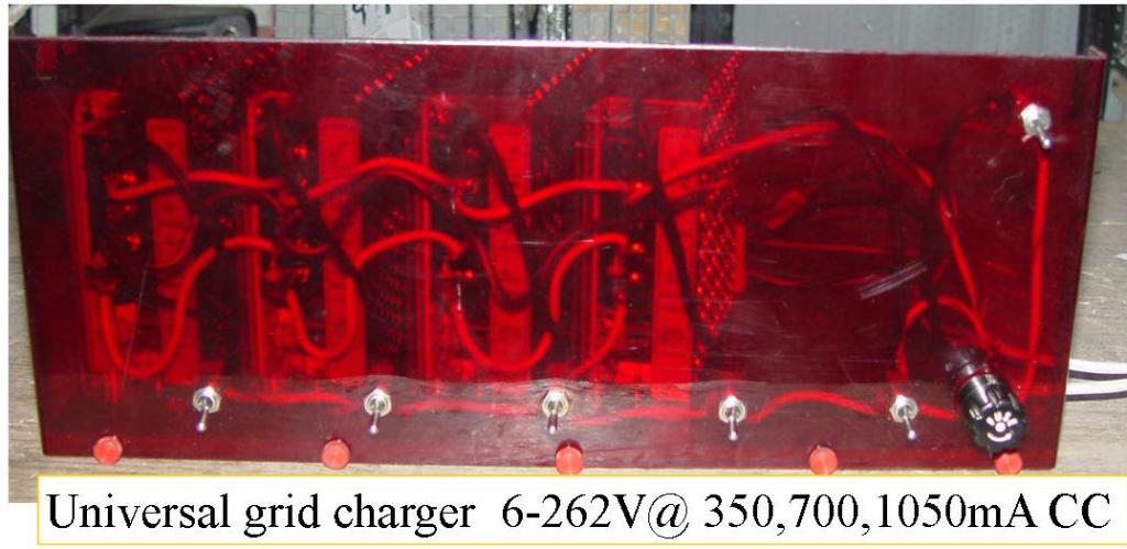 | | | wide range constant current charger |
I wired up the two stage grid charger and powered it up.
Put a switch on each of the four 48V supplies, and a master switch that turns on the two CC supplies.
A 6A diode across each of the power supplies output terminals so current has a way to get back to the CC power supply negative when the 48V supply is off.The diode drop about 2 V when all of the supplies are off.
Each of the 48V fixed supplies can be adjusted from 40-53V.
With all of the 48 supplies turned off, we have a 350mA and 700mA CC supply that has 4 diodes in series with it.
This gives us a choice of 350mA, 700mA, or 1050mA.
The current can be supplied over a CC range of ~6V to 46V.( 2V lost in diodes)
A single subpack to 5 subpacks.
Turn on one of the 48V supplies, and we add an adjustable 40-54V
Total CC range ~40V within a range of ~43 to 100V
(Half of an Insight pack)
two supplies ~83-154V (InsightII 100V pack)
three ~123-208V (Insight and Civic pack)
four ~163-262V (Prius pack)
5 or more to do any hybrid battery out there.
The CC supplies work perfectly in parallel, so in theory one could put 10 or more in parallel to get a 6-48V 7A+ power supply.
Lots of possibilities.
(Posted 1/30/2010 by mikey) |
IMA battery smart discharger | 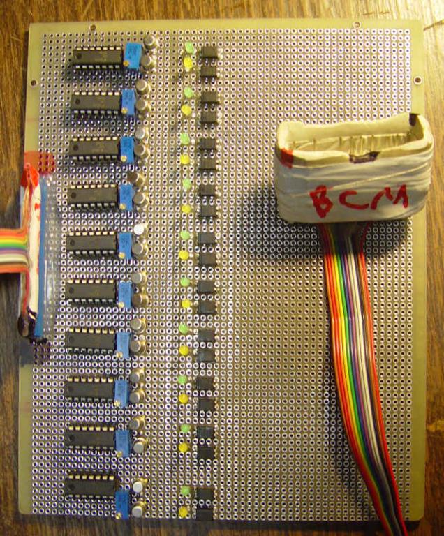 | | | smart discharger |
We will soon have a nice overnight charger, so the final component required for a fully automatic grid cycler is a discharge monitoring system that can accurately detect when any of the ten 12 cell subpacks that are tapped and appear on the BCM connector drop below 12Vor 1V/cell.
The same circuit will also detect a rapid cell drop off if it happens before the 12 cells get to the 1V/cell level as will happen when a cell reaches depletion before the rest of the cells in the 12 cell string.
Reading the BCM to get the cell drop out detection will be the best way to do the detection, but we are not sure that the BCM reports that information or if it simply terminates assist when the cell dropout is detected.
a totally independent circuit seems like a better solution at this time.
I started the project by mounting all the required components to a large perfboard. The circuit performs well, but one issue came up that I overlooked. The 160 ohm thermistors in series with this circuit will give false voltage readings because of the 160 ohm series resistance. The best solution I can think of so far would be to clip 1A fuses across each of the thermistors, thus making a safe but very low resistance tap to the battery during the testing.
Like all of this type of project, the devils in the details.
(Posted 1/25/2010 by mikey) |
Overnight two stage charger | 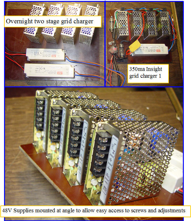 | | | Two stage charger takes shape |
While the 350ma charger provides a safe way to fully charge the Insight packs, It can take more than one night to get there. I decided we needed a charger that was faster but still retained the safe 350maCC final topping charge. The new charger will use larger 48V supplies, with two CC supplies in parallel as the CC regulator. Once the voltage gets to 165V, the 700ma supply will turn off, allowing the 350maCC supply to finish the job.
This will yield a 1.05A charge during the initial charging so we will have 3X the charge rate for most of the charge. The switch over point will be adjustable, and the charger will have a latching system, so that once the switch takes place, it will not go back to 1.05A even if the voltage drops, until it is manually reset, and the voltage is below the switchover point.
The supply will have a 4th 48V supply to allow the charger to work on Prius 208V packs.
I am missing the RS-25-12 fan supply, but should be able to wire it all up and get the switchover and voltage detect working on what I have.
(Posted 1/25/2010 by mikey) |
Hybrid Battery Repair | 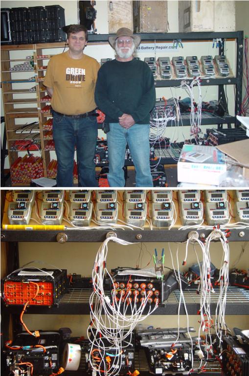 | | | Ron and Mike at Hybrid Battery Repair shop |
Ron from Hybrid Battery repair offered to give me several Civic and insight power electronics packages, so My buddy Paul offered to drive the 650 mile round trip in his Prius so we could check out Ron's battery rebuilding system and pick up the toys.
Ron has an effective system to cycle each 12 cell section of the packs while recording the AH capacity. After several cycles, he charges them and does an additional discharge at high rate on a single subpack while plotting the discharge curve on a computer. The shape of the curve is a good indicator as to the condition of the subpack.
The pack is reassembled, and charged as a unit after any sub-optimum subpacks are replaced with subpacks of
similar AH capacity to the rest of the pack, so all subpacks are as close to the same as possible.
Ron's website
Thanks to Ron for the power electronics and the tour of his shop.
(Posted 1/14/2010 by mikey) |
pack rebalancing test 1 | 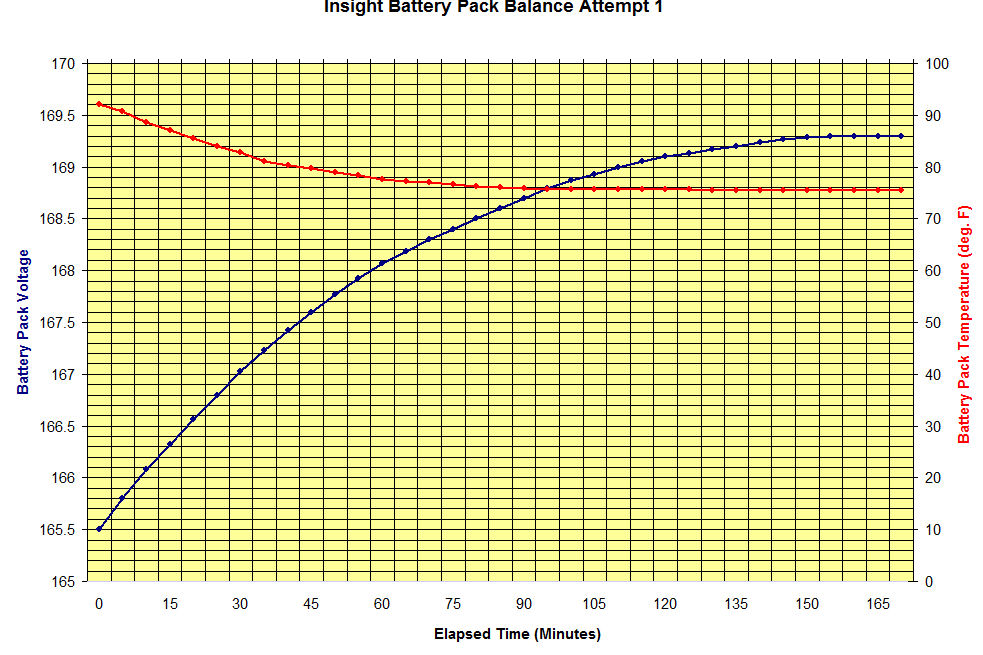 | | | Brians chart of charge cycle |
Cousin Brian (nemystic) drove down with his 2000 silver Insight for my first real rebalancing test.
Brian has a MIMA system, so he was able to charge the pack on the 60 mile trip to my place to the max that the system allowed, which was over the top of the SOC gauge.
This graph clearly shows the leveling off of the voltage rise when we approached the 100% SOC point.
The pack temperature was initially over 90F from the MIMA charging on his trip down, but once we got the fan and the charger connected and charging, the temperature fell to about 77 which was the ambient temp and stayed there for the whole test.
(Posted 5/24/2009 by mikey) |
current indicator | 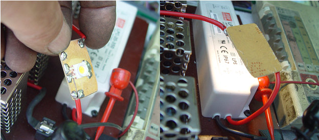 | | | 1 Watt white led as a current indicator |
I added a 1 watt led, rated for 350ma, which will drop the output voltage a bit, and light up when the pack is being charged.
I have blown out several leds on the first pulse when the charger was connected to the pack. A 20 ohm 5W resistor to shunt some of the current around the LED and run it at a lower current should fix this problem.
(Posted 5/22/2009 by mikey) |
Grid charger/Balancer 1 | 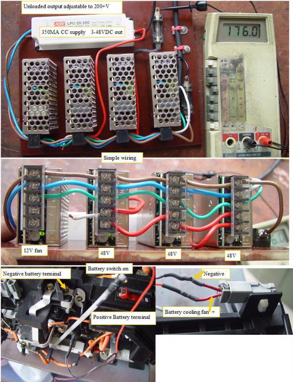 | | | Grid Charger/Balancer test 1 |
The Insight battery packs can be safely charged to the 100% SOC, and held there so the weaker subpacks get a full charge, and therefore giving all cells a full charge.
The HV at constant current made this charger difficult to buy off the shelf. By combining isolated constant voltage switching power supplies with an isolated constant current led power supply, we can assemble the supplies to build a charger to safely charge the HV pack of any hybrid car.
I built the charger with off the shelf low cost switching supplies from the Meanwell company. The last supply in the series string is a 350MA constant current supply that can swing from about 3V to 48V while maintaining a constant 350MA. The three 48 V constant voltage supplies that are in series to raise the voltage are adjustable from 42 to 54V.These supplies can adjust the max voltage we can reach once the CC supply reaches it's max voltage. 42V*3 + the CC 3V to 48V will allow the constant current to be maintained from 129V to 174V if the CV supplies are all adjusted to 42V each, and from 162 to 210V if they are all adjusted to 54V.
If the constant voltage power supplies are chosen and adjusted to 48V less than the max voltage we want to see once the charge is complete, the charge will rapidly drop from the 350ma to a lesser value.
I would recommend that the the three CV supplies are all adjusted to their minimum, so the charge will taper off after the terminal voltage reaches 174V, which is an average of 1.45V per cell.
Schematic of Basic grid charger/balancer
I started charging the pack at about noon,at an initial voltage of 152.3V. I turned the charger off at 1AM with 170.7V This pack had been sitting in the shop unused for at least 6 months.This morning the pack voltage settled back to 163.4V. The voltage rate of change during the charging was about .1V per 3 minutes, but I did not record the details. A definite slowing of the voltage rise began to be noticed about 11PM and 169V, and I saw the voltage start to dip by .1V at about 169.7.
*********WARNING THE POWER SUPPLY AND BATTERY CAN KILL YOU. DO NOT ATTEMPT THIS IF YOU ARE NOT PROPERLY TRAINED TO WORK ON HV SYSTEMS****************
*******WHEN CONNECTING THE CHARGER TO THE PACK, THE hv SWITCH MUST BE OFF.*********************
*************** THE NEGATIVE TERMINAL OF THE CHARGER CONNECTS TO THE NEGATIVE HV TERMINAL, BUT THE POSITIVE CHARGER CONNECTS DOWN ON THE SIDE OF THE PACK AT THE PRECHARGE RESISTOR/PRECHARGE RELAY CONNECTION POINT AS SHOWN,NOT AT THE TOP TERMINAL***********************************
(Posted 5/9/2009 by mikey) |
fast pack rebalancing 101 | 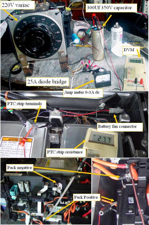 | | | Rebalancing off the grid |
Ron Hansen drove his space alien green insight up from NY, so we could try to rebalance his battery pack.
He was having very frequent negative and then positive recals, and almost always saw a charge.
The car was rebuilt from a salvage, so Honda would not do anything for him. The car sat for over 6 months which probably contributed to the problems.
The IMA code of death kept coming back even if reset.
I gathered up the required components.
220V variac
25A 400V diode bridge
300Uf 350V cap
3A dc ampmeter
custom HV connection probe
several DVM's
We wired up the power supply and confirmed that I could get 0- 250vdc output range.
We flipped the pack switch and found that the pack was at 154V.
With the pack HV switch off, I attached my custom HV probe to the precharge resistor lead (+) and an alligator clip to the negative terminal. We raised the variac voltage until it was at the same 154V so we would not get a surge when the charger was applied to the pack by flipping the main switch.
I made up a fan connector so I could run the battery fan if required from an adjustable DC lab supply.
We also connected an ohmmeter to the PTC strip ends so we could watch the strip resistance change as the pack warmed up.
I started with a 2A charge, so we could get to the 100% SOC point as quickly as possible. We watched the battery voltage raise, and tweaked the variac voltage to maintain the 2A charge.The PTC strip started our test at 22.9ohms, which represented about 85F.
After 5 minutes or so, the PTC strip resistance started a gradual raise, and the pack voltage continued to raise.When the PTC strip got up to the 30 ohm range, I pulled the battery fan and used my non contact IR thermometer to see that the cells were at ~110F.I put the fan back in,turned it on and taped around the edges so it would draw air better. I used a digital thermometer to measure the outlet air temp, and found it at ~ 100F. The fan at 12V was really pulling a lot of air through the pack, so the PTC strip resistance rapidly began dropping towards the starting resistance, and the fan outlet air quickly dropped to ~88F.
Conclusion, with the fan running at 12V, there will be almost no measurable temperature rise even when charging at 2 A.
As the pack approached the 167V voltage we dropped the charge current back to 500MA, and left it there. The voltage of course dropped back a bit to 165V when the current was dropped, but after another 1/2 hour at 500MA, it pretty much stopped changing and settled at 168.9v.
We determined that the best way to determine when you are at the 100% SOC point is when the pack voltage stops raising. A simple rate of charge vs rate of change of terminal voltage determination should be all that is required if an automatic charger/balancer were to be built. When the high rate charge pack voltage rate of change slows down, we switch to the trickle rate, and again wait for the rate of change to actually stop changing, then we soak for say 1/2 hour and then stop the charging.
Ron drove back to NY, and found that the pack behaved much differently, and the charging would work much more normally. Unfortunately he will be not be able to drive the car for the next 3 weeks due to a medical issue.
We will have to wait 3 weeks to get the full report.
Ron has since started a hybrid battery pack rebuilding service.
(Posted 9/7/2008 by mikey) |
The HV panels can bend and will shock the S**T out of you | 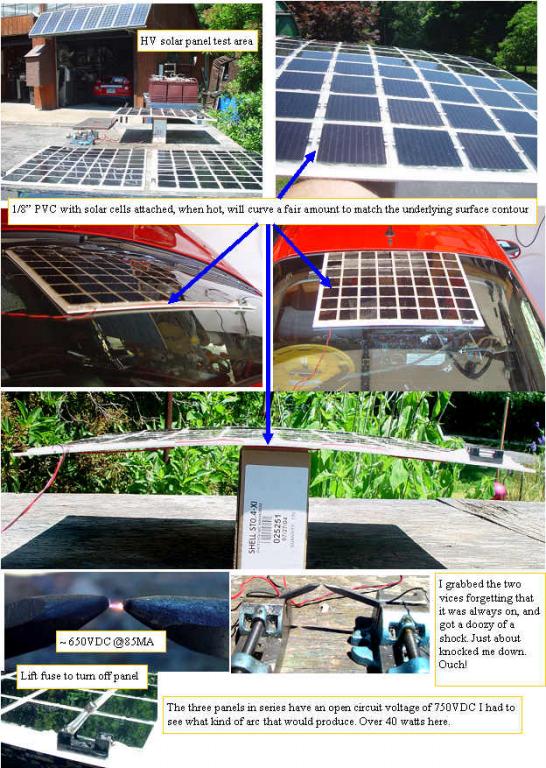 | | | Testing the HV panels |
The three HV panels have cured enough so I could start to play with them. I happened to lay one on the rear window of my insight in the full sun, and observed later that the PVC softened a bit when hot, and formed to the shape of the rear window. A few more test showed that even with the cells glued on, the silicone allowed the slight give in the bond required for the slight shape change.Cool.
I will have to let it take the shape, then calk the cracks with silicone. This should help lock in the curved shape.
I had to try connecting the 3 panels in parallel and series to see what they could do. I got the full 255MA SC, and 250 v OC that I expected. The series test got us up to 750 V, @ 85MA. I set up two small vices each with a graphite rod, and connected the + panel output to one, and the - to the other. The panels could sustain a continuous 1/8" arc, that could melt wires.
I stopped the arc, and walked away to tend anouther experiment. Several hours later, I was going to clean up the panels, and without thinking, I grabbed one vice in each hand. Holy bat dropings, what a shock.
I handled one at a time from there on out, with a very healthy respect for what 10%(cell efficiency) of 7.8 square feet of solar energy could do to me.
I leave the leads twisted together on the panels now. They can't bite me that way.
(Posted 7/16/2008 by mikey) |
Building the HV probe for the + attachment | 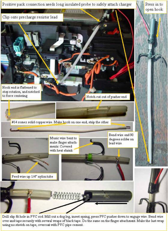 | | | How to safely tap onto the battery pack + terminal |
If you looked at your car and said how can I connect to that bottom point where the battery pack positive input resides without shorting something out, or getting killed by the HV, here is how I did it.
I looked on line to buy long clip on test probes, and did not like the selection or price, so I rummaged in my stuff pile, and came out with a piece of 1/4" OD nylon tubing, a piece of #14 romex, a 1/2" PVC rod, and a compression spring.
I cut the nylon tube to the length of the required probe. I squeezed one end in a vice after inserting a 1/8 " rectangular spacer. This cold formed the tube so it was rectangular. I stripped the #14 wire, and formed a tight hook in the end.I cut a V in the long side of the nylon rectangle, to lock the probe onto the resistor lead.
About 1" from the other end of the tubing I used an exacto blade to cut out a rectangle that was the same width as the wire was thick, so the wire slides in the slot.
I fed the wire up through the tube and when it came out the slot, I pulled the hook into the full retracted position, and at the top of the slot, I made a 90 degree bend in the wire, stripped the end, and soldered on my red + wire.
I put the PVC rod in a vice and drilled a .266" hole in the end to a depth that would just start to compress the spring when the assembly was put together. I used my milling machine to make a dog leg in the PVC rod, so the wire would lock into the dog leg. You should be able to carve the dogleg with an exacto knife, just don't cut your self.
The spring is dropped in the PVC rod and the assembly is pushed together compressing the spring then engaging the wire in the dog leg.
Once the operation is tested by pressing the PVC towards the nylon tube, a piece of music wire was bent and wound to a shape like a hypodermic needle finger hook. A wire tie was tightened on the nylon tube just below the fully compressed PVC pushers fully extended position. The finger hooks are covered with a small diameter heat shrink and the tightly taped in position with black tape.Wrap 4 or five wraps tightly, then one without stretching. Bend the wire over the PVC pusher, then tape the same way, 4-5 tight wraps, one no tension. Then using PVC pipe cement coat both tape jobs with a thin even layer. This will bond the black tape together so it will never get sticky or loosen up.
One custom HV spring loaded attachment probe.
(Posted 7/16/2008 by mikey) |
Building the Solar HV charger/rebalancer | 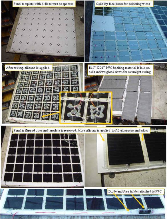 | | | Building a HV charger/rebalancer |
Finally got some more HV solar panels built. To make the process simpler and more reliable, I determined that a fixture to hold the cells in position while connecting wires and gluing with silicone was required. An 18.5" X 21" expanded PVC panel was drilled and fitted with 4-40 self tapping screws, with a pattern that positions the cells uniformly. The fixture will work up to 56 cells (HV panel). The cells are laid between the screws, and short stranded wires are used to connect the whole 56 cell array in series. The + and - end points have heavier wire. The rear of the cells each have four silicone bumps applied. and the backing PVC is carefully laid in position over the fixture and weight is applied. Overnight curing will fix the cells position and allow the whole fixture/panel to be turned over, and the fixture is removed.
Silicone is applied to all cracks between the cells as well as around the edges, and the panel is left on a flat surface for several days of curing.
The positive output is run through a fuse holder, and an isolation diode.
This single panel charges the pack at a max of 85MA. A dead pack would take over 80 hours to fully charge with this low current.Three of these panels in parallel would take about 26 hours to fully charge a completely dead pack.
Fortunately the packs usually are in the 20-80% SOC range. A pack that is at full on the Insight SOC gauge is about 80% charged, so it can still take ~ 1.3AH or about 15 hours of sunlight with a single panel, and a bit over 5 hours with a triple panel to reach the equalization stage.
Longer is better, as we want to bring up any cells that are not full, and the low current will not damage the pack.
(Posted 7/14/2008 by mikey) |
Insight Battery pack Solar charger/rebalancer | 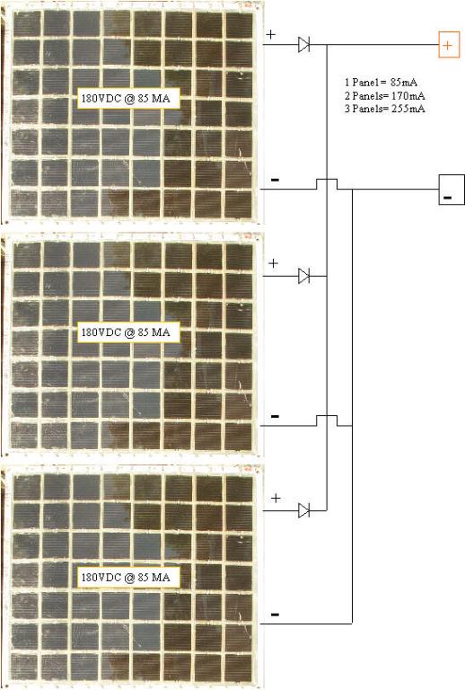 | | | Danger this HV panel can electricute you |
Many Insight battery packs develop an imbalance.
Sitting at a constant SOC for a long time without charging or exercise will allow the individual cells to self discharge due to internal leakage. This leakage is usually slightly different on each cell, so given enough inactivity time, the pack will develop a big difference in charge between the cells.
The Insight system stops charging at 80 % SOC, so the imbalance never gets fixed by an equalization charge.
If you fully charge a pack with a constant current of 85 -255 MA, this constant current will bring up the weaker cells by giving all cells a 100% charge.The cells are rated for 500 or more full cycles, so an occasional one or two will not effect the pack life.
It is very likely that many packs that have become imbalanced, and were frequently recalibrating before throwing an IMA code can be revived by rebalancing.
a solar pack charger that provides the required current at sufficient voltage to do this recharging and re-balancing is described here.
The solar charger needs to be able to produce 180VDC to fully charge the battery.The panel output terminals with no load will be at 250VDC. this panel delivers about 15 watts of power.
Using this procedure exposes you to the full pack voltage, so you can get electrocuted if you get your self across the HV, of either the pack, or the solar panels.
I will be testing this system on some local people that have recalibrating battery packs. An AC powered charger/balancer is on the list of projects, but will not be as safe, or as green as this purely passive PV method.
(Posted 6/23/2008 by mikey) |
Equilization test #1 | 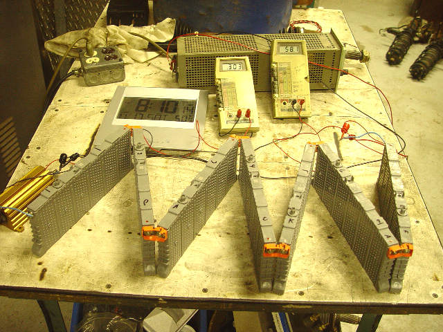 | | | Equilization charge at 300ma |
Ian and I took one of my 7 Seven subpack Prius based packs and after discharging it to lower the SOC by 10-20%, set up a constant 300MA charge system, and logged the voltages across each subpack. We spread the packs out so that cooling would be the same on each, and measured the temp of each cell when we took the voltage measurement. The initial condition showed a max of about .07V difference between the subpacks. The charge ran for 14 hours before I saw the sides of the cells start to bulge, but I never saw any measurable temperature rise.
The Subpacks seemed to equalize starting at 7.85V/subpack, where all of the subpacks were at that exact voltage. I continued to charge up to 8.47V/subpack where all the subpacks remained at the exact same voltage.
Next I will discharge the series string and log the voltages during discharge.
(Posted 11/19/2007 by mikey) |
Battery pack rebalancing? | 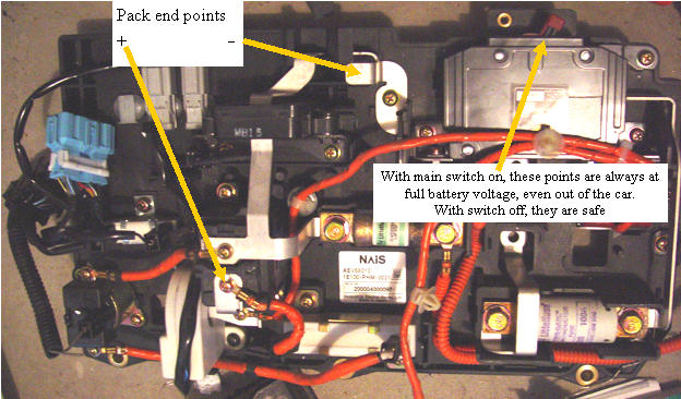 | | | HV taps WARNING this will fry you. |
WARNING, the batterypack can and will kill you if you contact the hot terminals, so do not try this if not fully comfortable with working on HV DC circuits.
A look at the Saturday workshop efforts will show that Ian has rebalanced the silver Insights battery pack using the Triton smart charger. A lot of work, as the pack must be pulled and disassembled. James Frye from Reno, has duplicated the procedure for his consistantly recalibrating pack, and we await the results.
Another approach to this rebalancing has been suggested by Armin Kusig who has been grid charging his battery pack each night with a gentle 300MA charge. Since the info on NIMH batteries would indicate that a low current charge of the batteries should not do any damage or substantially reduce the life of the batteries, it may be a better way to do a rebalancing.
The battery pack current control/interconnect board allows access to both ends of the battery pack, and therefore is the best place to connect a series charger. The indicated points are only HOT when the main switch is on.We will be building up a constant current charge system to give this a try, and will report the results here.
(Posted 11/17/2007 by mikey) |
|

|