Plugging into the SUN
In the 70's when we had to wait in line for gasoline, I saw first hand what happened when supply fell short of demand. I live at the end of the power line,and thanks to falling branches,ice storms and such, I have had to go without power for over a week more times than I can remember.
I sometimes reflect on the fact that in many places in todays world, the poor people are living their whole life without electricity, or any of the luxuries that we so depend on.
The modern world has become so dependent on this supply of energy that we find it difficult to see a world without it.
This blog will document and follow some of the solar and alt energy projects that I am working on.I hope to eventually replace the gasoline engines on all of my yard maintenance equipment, and convert as much of my energy needs to solar/electric.
The Boy Scout motto "Be Prepared" is a very good piece of advice for all of us.
Blog starts at the page bottom.
Plugging into the sun banner High res
|
Solarfest is next weekend so it is time to tweak the tools | 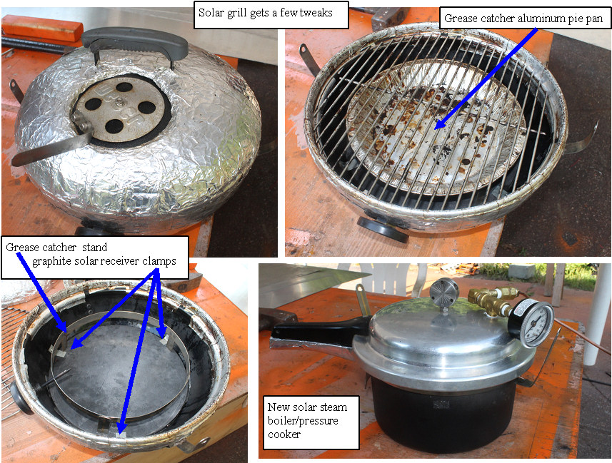 | | | Getting ready for Solarfest |
After using the solar grill for a year, and seeing what worked and what were problems, I made some important tweaks to the grill.
1.The graphite solar reciever was secured, so placing the grill on a surface will not push the graphite into the grill
2. Grease from burgers and other meats were falling on the graphite, and then flowing out and dripping on the mirrors, messy problem. I made a stainless steel holder for a standard 8" aluminum pie dish, which works great at keeping things clean.
3. Made a new solar pressure cooker, with two covers, one lets it work for cooking, the other has steam gage and copper steam line so we can use it to make distilled water, or run a small steam engine.
Continuous improvement, so every year it gets easier and better.
(Posted 7/13/2014 by mikey) |
Lightning the super fast EV minibike | 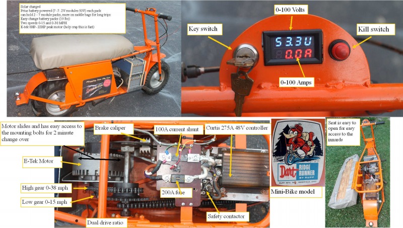 | | | Lightning the EV minibike |
Have always wanted a small but powerful electric vehicle to bring to the solar events. What better way to get people turned on to the fun of a fast quiet Ev.
In preparation for Solarfest, I gathered up an e-tek motor (8HP continuous, 22HP peak) a 275A 48V curtis speed controller (from the e-wheel)My new 48V prius modules, and was looking for a vehicle. My Buddy Dan dug in his garage and came up with a big minibike that his Dad used for hunting in VT. The frame was extended, and a super aggressive rear tire made it able to climb through the woods. Dan donated the machine to the cause, and I went at it with welder, chain, and it went together pretty fast. I made the base machine so it can carry 2 of the 48V prius modules.
Mounted one of the small Chinese Volt/Amp meters so I could see the current and pack voltage. The original gas engine had a reeves drive (snowmobile)type variable ratio drive, so I just removed all that stuff. Made a motor mount for the e-tek, and a battery holder that accepts the same 48V modules as the telephone truck and the yard electric buggy.
The day I first tried it, I almost went over backwards, the thing sucks well over 100A, and just jumps when you twist the throttle.
I put in two sets of sprockets, a low speed high torque that gives a 10:1 reduction, and a 0-15MPH speed,and a high speed set, 4:1 ratio, that gives 0-38MPH, also with very fast acceleration. Sucking 150A out of 2 prius modules will not yield much range, but if you can control your self,it zips along nicely on flat ground with only 2-3 A.
The machine weighs ~ 190 lbs with 2 battery packs (19 lbs each), and we have tried it with 2 people on it (~ 350 lbs), and even in high gear, it just jumps when you ask it to go.
This is the ultimate EV demo, as all the components are right there easy to see, and it really brings in the kick in the pants acceleration that we all love. Thanks Dan
(Posted 7/11/2014 by mikey) |
The new batteries are finally installed and working | 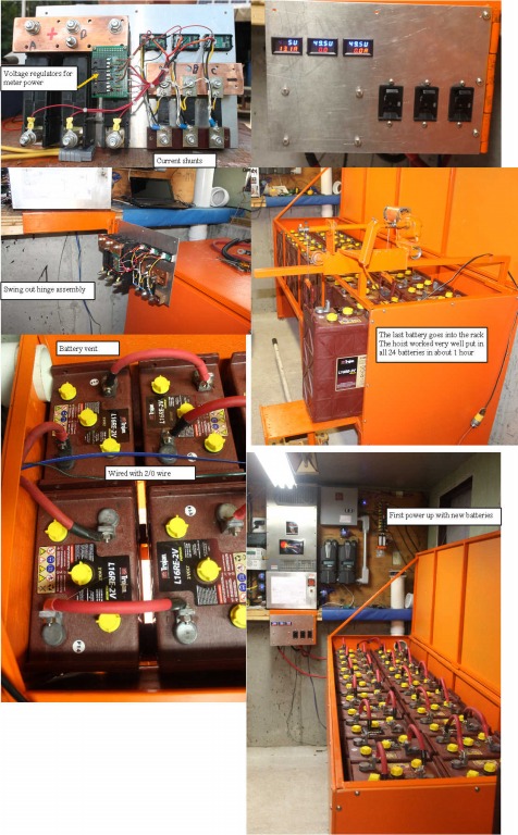 | | | finally the pack is working |
Got all the wires cut and terminated, made the battery combiner panel with 3- 250A DC breakers, and three of the cute chinese volt amp meters.
Like any big project, the things that needed to be done to get there, took longer than building the battery rack. Just moving the old batterys and the racks took most of a day. Happy the new batteries are now earning their keep.
(Posted 7/11/2014 by mikey) |
Finally nearing completion of the battery enclosure | 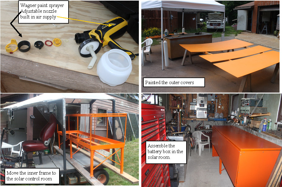 | | | Almost ready to install the batteries |
Spent several days cutting fitting the plywood covers for the battery enclosure. The thing needs to be air tight so I can vent the fumes with a blower. I built the thing so there is room for air to pass between the batteries, which will hopefully give them better cooling. Still need to make two movable racks for the two sets of 8-6V T105, so I can use them all. Why does everything take so long.
I sprung for a Wagner paint sprayer. The spray gun is powered by a vacuum cleaner type blower which is right in the unit. It works pretty well with thick latex paint that I am using, and wow does it put down some paint when you adjust it for high speed.
(Posted 6/25/2014 by mikey) |
Getting too old to be slinging 120 lb batterys into the rack | 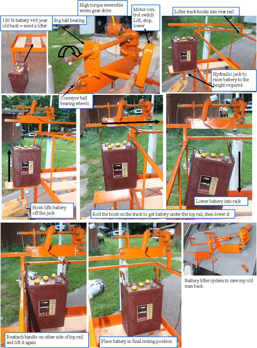 | | | Mikey the old man battery needs custom battery hoist |
Ok, I made a nice rack for the battery's, but the batteries are so heavy that I am afraid that I may wreck my back loading them onto it. I can lift them and stand straight, but that only gets them half way to the height required to clear the lip of the big angle, and the top support rail only allows ~ 1/2 inch of clearance, so having full control of the weight at all times is required to pass the rail and get the battery in the rack. After looking at transmission lifts and other off the shelf solutions, I decided that I needed to design and build a custom lifter to do the job.
Went digging in the stuff box, and found a nice worm gear right angle Dayton gear motor which has a very high gear reduction, some ball bearing conveyor rollers, and misc shafts and square tubing.It is important to have a worm drive so the weight of the battery does not back drive the motor. I can lift it precisely due to the high gear ratio, and when I stop, the battery just stays there.
The top rail for the lifter clips into the rear rail of the stand, and the motor driven shaft is set at an angle so a wire rope can be dropped past the top rail on both sides. Made some clips that the battery handles fit into,with offset cable attachment points so the battery stays level so the hoist can be simple clipped on the battery handles.
Getting the battery to the best starting height is accomplished by a custom table that jacks into my big hydraulic jack.
The rope handles on the batteries allow me to grab one of the handles from the inside of the rack top rail, and the trolly lets me move the battery within the stand. I put it down, grab the other handle with the hoist from inside the top rail of the stand, and then easily move it to the final resting position.
It works well, Took 2 days to build,and 8-12 years from now when I have to start replacing batteries(optimist), and am 75-80 years old, I will really appreciate this tool.
(feedback)The lifter worked very well,with all of the batteries being put in place on the rack in ~ 1.5 hours. I developed a technique that allowed me to put the battery in place so only a single lift was required to get it in the rack.
Need to enclose the rack with plywood and make a lift up cover, and I will be ready to plug the new batteries into the system.
(Posted 6/17/2014 by mikey) |
Main structure of battery rack is finished | 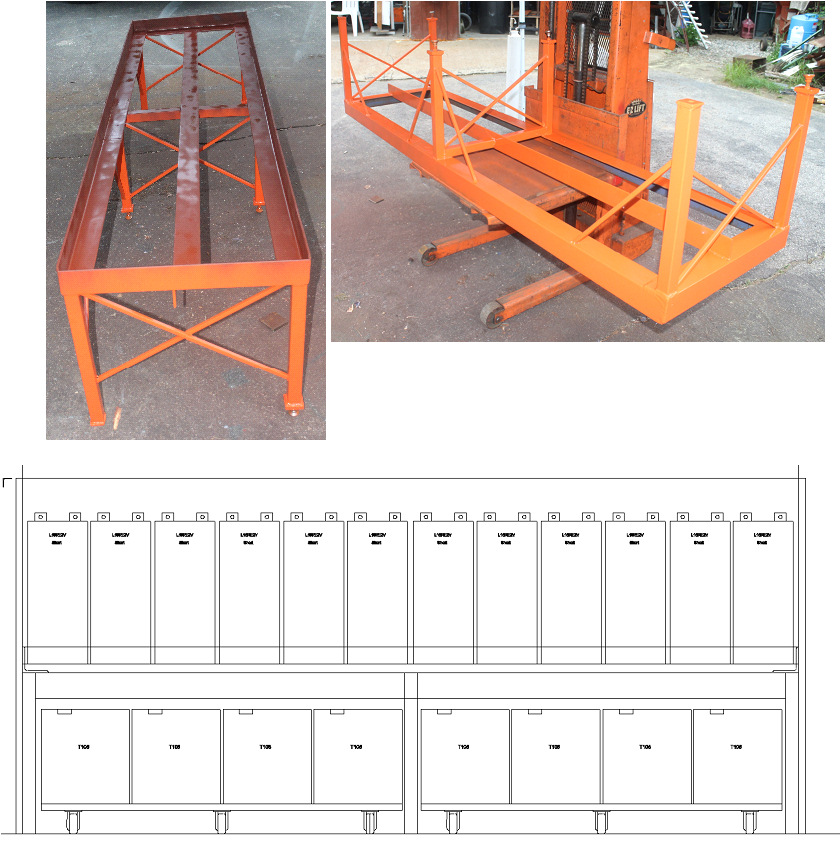 | | | building steel rack for batteries with solar power |
Got to test my solar systems ability to charge batteries and run my MIG welder at the same time, while building a strong battery rack for the new guys.
Had no problems getting the batteries to 100% and powering the welder and shop even though the day was very cloudy.
The 160 lb rack will have 2800 lbs of the 2V batteries on the top shelf, and the bottom will be two of my 48V moveable racks, totaling another 1500 lbs. The whole thing needs to be sealed so it can be vented, and I am going to provide cooling or heating provisions in case I find that will be required.
Welded and machined for free with solar generated power. Yea!
I am 68 now, and hope to get 10 years out of the batteries, so that would mean that I will be 78 when the batteries will need to be replaced, hopefully with Lithium or some other battery with better cycle life. The rack looks like it will work nicely, but after struggling to move the 120 lbs batteries around, I decided to build a simple hoist to lift and allow removal of the batteries from the top of the rack, as one person needs to be stronger than I to install or remove them single handedly.
(Posted 6/10/2014 by mikey) |
Adding some new batteries | 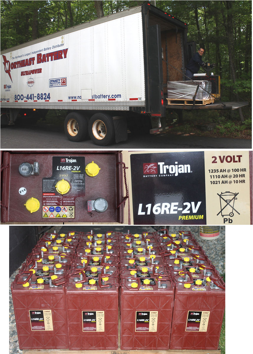 | | | increasing my battery storage |
After living with the system for several months,it was clear than I was not going to realize the full potential of the system with the 16 trojan T105 golf cart batteries.
After doing some research into the most bang for the buck, I settled on the trojan L16RE2V 2 V cells. They are rated at 1100 AH @ the 20 hr rate, compare to the golf cart batteries which are 220AH.
Trojan just introduced in march what it calls its Smart Carbon construction for Renewable energy batteries. This is supposed to add 15% to the battery life when used in RE applications.
The problem with buying big batteries is getting them home, so a big part of my choice was that a local battery supplier had 24 of these batteries in stock, and was willing to deliver them for free. Only catch was that they bought them before Trojan
introduced their smart carbon technology, so they were in a position to want to get rid of the old stock. The street price of the batteries is $364 each, but they let me have them for $300 each,so the 15% possible life improvement of the new smart carbon batteries was given to me as a discount, and hopefully by careful maintenance I can get some good life out of them.
An important thing to note here, is the construction of the cells.
The L16RE batteries come in a 330AH 6V version, or a 1100Ah 2V version. The case is exactly the same, and the battery still has 3 cells, the difference is that the inner cells are either series or parallel. The down side is that you have three cells to check and maintain even though it is a 2V cell. Turns out that they make an Industrial battery of 1500AH that is a single cell, but that cost close to $1000 each.
Time will tell if I made the best purchase. Now I need to build a big battery box with vents that will house all of the batteries.
(Posted 6/9/2014 by mikey) |
Hot water test 2 | 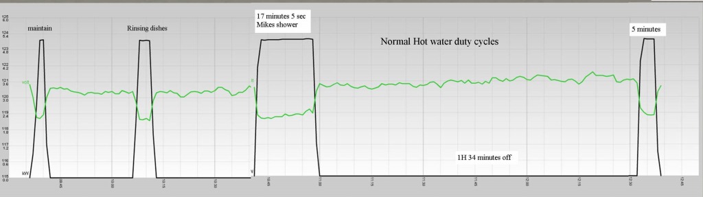 | | | normal hot water cycling |
Have been looking at the options as to heating the hot water, and think that at least for now it is best to switch the water heater to grid once the solar has finished for the day, or on a clowdy day, and to run it on the batteries during good solar days.
I an still trying to get the batteries in shape, and it looks like the short 5 minute burst of 130A draw to heat the water during the day, as well as the desulphater running continuously is kicking them back into shape. Today for the first time I am seeing all the cells in both banks the green "good" area of the SG tester.
The last test was 20 days ago, right before I started running the water heater during the day. and I saw all the SG have risen by at least .030 with some over 0.07.
Have been doing a 3 hour absorb at 58V every day, then letting it sit in the float zone at ~ 53V
Still testing the hardware for the load manager, and will start the software soon.
Many outdoor spring chores to do first, and I want to get the lithium battery control boards made and mounted, as well as getting the electric yard buggy and bucket truck running on Prius modules.
(Posted 4/25/2014 by mikey) |
Hot water tank as energy storage component test 1 | 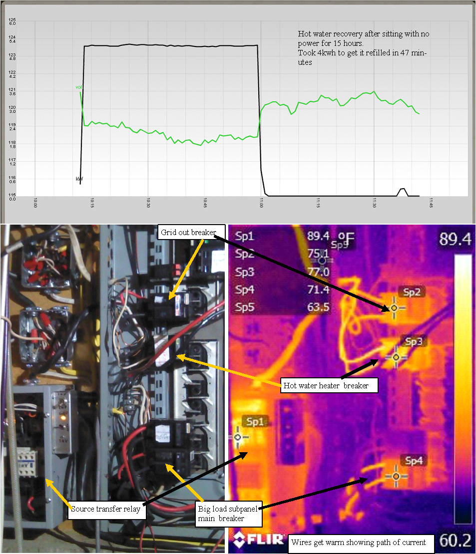 | | | Running some current and heating water |
To better understand the dynamics of using my hot water tank as a energy storage load, I turned it off overnight, so I could see how much power it took to get it back to the setpoint.
The heaters were turned off yesterday when the sun went down, and turned back on 15 hours later. It took a bit over 4KWH to recover energy lost. This was with minimal hot water use.
Since this was also the first big load that was run through the new transfer relays. I got out the thermal camera to see what was warming up. Looks like reasonable temperatures. The electric range is the next big load I will move over. Am looking at the best construction method for the high current solid state relays current sensing system. Luckily I only need to make 8 of them.
(Posted 4/13/2014 by mikey) |
The transfer relay is wired in and working. | 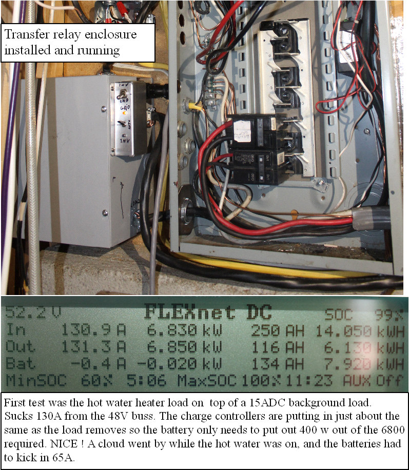 | | | big load buss is now running through the transfer switch |
Got the new transfer relay box mounted and wired in. This powers the big load manager buss in the main panel, from either the grid or the inverter, and can be remote controlled. It was a sunny day today, so I moved the hot water heater over the the new high load buss, and ran some hot water to see how the system would handle it.
It took almost 7KW, and well over 100Afrom the 48V system to run the big heater, but the solar input and the charge controllers were able to keep up and the heater cycled off after 10 minutes.
Will leave the hot water heater off all night, and recharge it once the batteries get recharged tomorrow, and see how much recovery is required. The system monitoring to best use the available power is going to be tricky to tweak due to the wide variability in solar input.
(Posted 4/12/2014 by mikey) |
AC source transfer relay is finished | 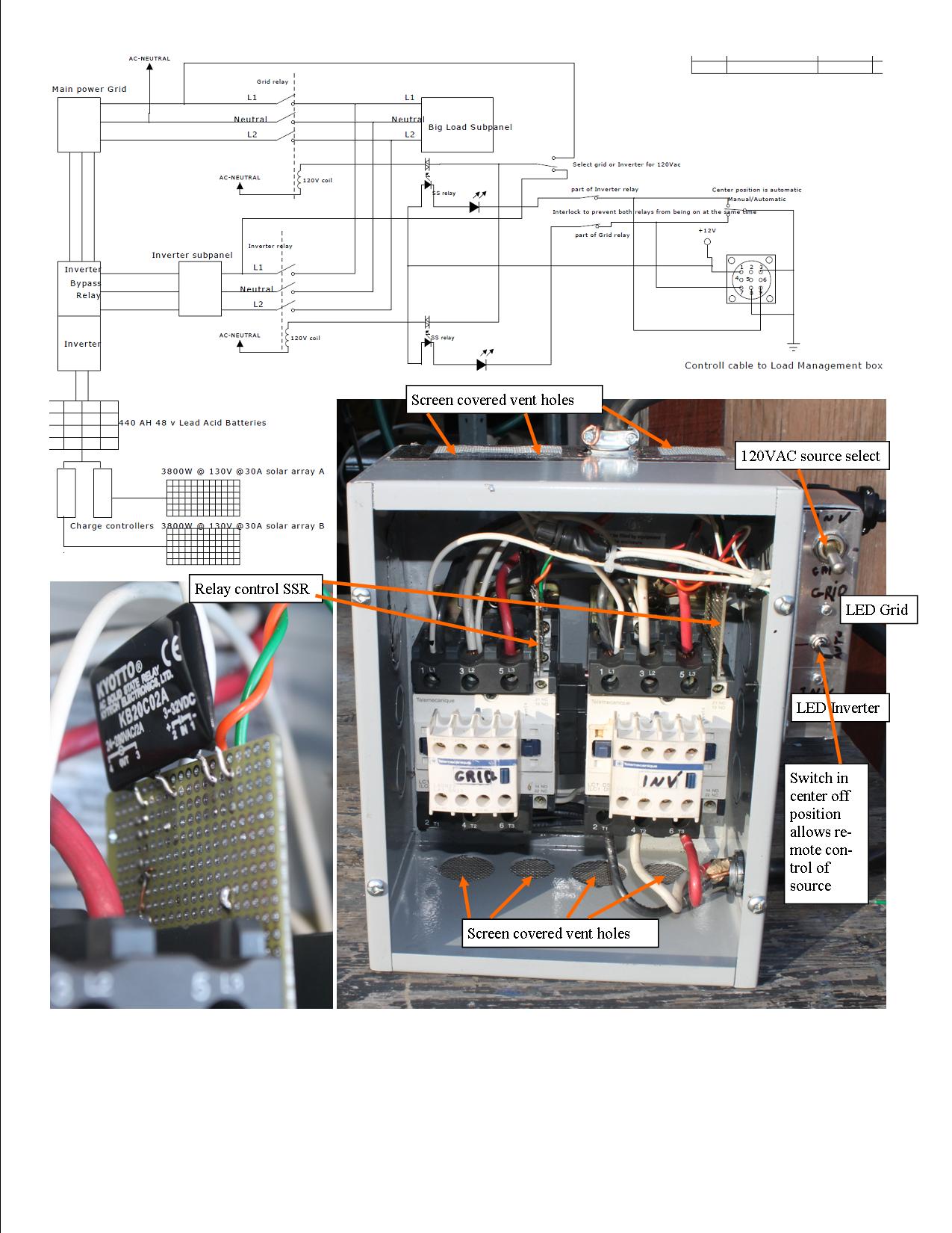 | | | transfer system is finished |
Finally got the big 50A transfer relay system built.
The big relays need 120VAC to operate the coils, so I used 2 of the same 2A solid state relays that we used on the grid charger to turn them on and off. The SSR feature opto isolated dc inputs that will operate from 3 to 32 VDC. After doing some measurements, the opto input seems to be current regulated at 10 ma, so it was easy to get another series led to act as an indicator with no need for a resistor. Will power the optos with 12VDC
Since we still needed 120VAC for the relay power, I put another SPDT switch so the ac can either come from the inverter output or the grid input.
I used a 9 pin connector (grid charger) for the source control lines and 12V power, which will run to the load management computer box.
The mounting location for this transfer box is not very accessable so I had to fully wire the box before it is mounted.
(Posted 4/10/2014 by mikey) |
Assembling the parts for the load manager | 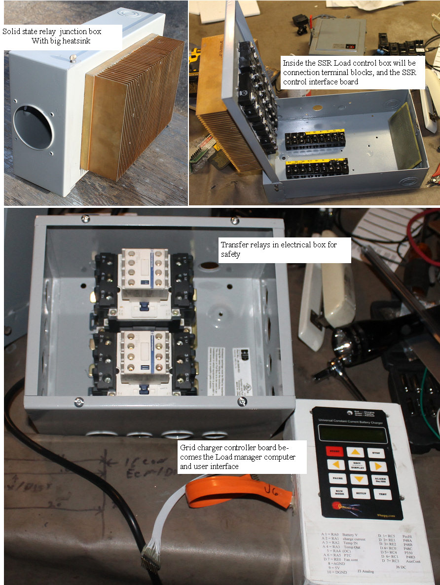 | | | gathering the parts |
Started by building a modified electrical box with giant heat sink on the cover. Added 8 big Solid State Relays (SSR), and have ordered some interface IC's.
I built up a grid charger computer board to use as the controller.
The big transfer relay assembly was mounted into another electrical box, in preparation for the final wiring.
Next step will be to wire it up and get all the electronics to work and get the rudimentary program written.Until then, I will be the load manager, and learn what works and what does not, so when we start writing the program, I know what it needs to do. Would be great to be able to get the hourly skycover predictions from the National Weather Center, as a way to know in advance what to expect for solar input.
(Posted 4/3/2014 by mikey) |
50A 600VAC transfer relay | 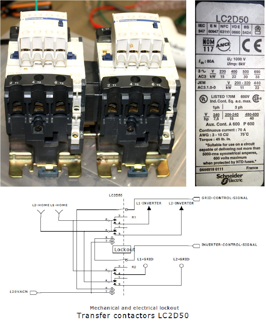 | | | lucky find in the stuff box |
The big loads wired to the new isolated section of the breaker panel will want to be be powered by either the inverter or the grid,depending on the availability of the sun to keep the batteries up during the high current draw required.
Need to remember that to get 10 amps at 240VAC (2400Watts) from the inverter,the batteries need to put out 50A @ 48V.
To carry the high AC currents I needed a big DPDT relay or other safe way to switch the load L1 and L2 lines to the desired power source.
After not having much luck looking on line for a big generator transfer relay, I dug through the parts salvaged from the big motor driver units I got several years ago, and found just what I was looking for.
This dual relay is designed to reverse a big 3 phase motor, so it has all the contacts required to do my grid to inverter transfer.
List price is $600, so I just saved a lot of money since I got it for free, and got a very high quality industrial relay well suited for the task. It features both mechanical and electrical safety lockouts to prevent both relays from being activated at the same time.
A good example of why saving cool components from the scrap yard can save you a pile of money.
(Posted 4/1/2014 by mikey) |
preparing to connect the big loads | 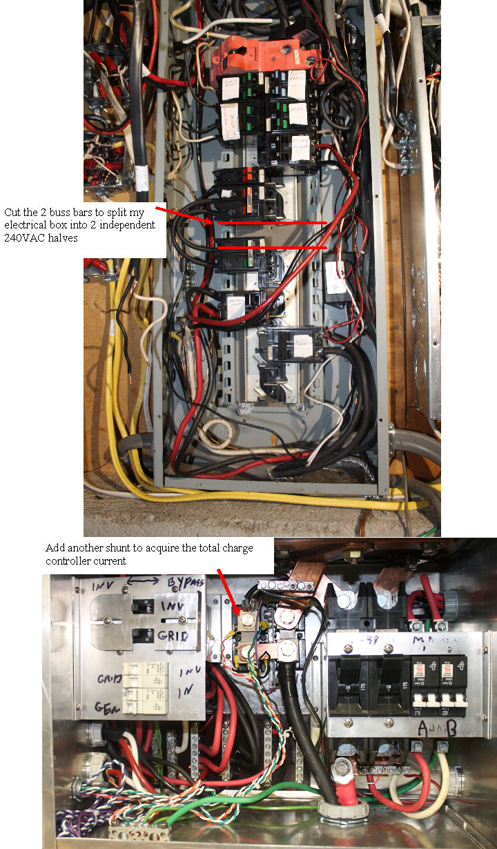 | | | splitting the main electrical panel into two sections |
My big breaker panel is nearly empty, and my new breaker panel is nearly full, so after looking at all my options, I chose to cut the main buss bars in the big panel to break it into two separate panels in the same box.
Doing this live was not an option, so I turned off at the main breaker and the inverter, and rigged up a 48V battery from some prius subpacks, and powered my 1500 watt sine wave inverter, to power my cut off grinder to make the cuts, once they were cut, the bottom section of bus bars was easily removed, so the buss bars could be shortened. I don't want to be able to bridge the gap with a 240V breaker for safety reasons.
The photo shows how the two sections are coupled with a breaker on each with jumper wires for L1 and L2.
This is temporary. the final system will allow this second breaker to be powered buy either the grid, or the inverter, and the loads will be enabled or not with high power solid state relays.
Added a second current shunt so the combined solar charger output can be used to determine the battery capacity, and many other related functions. Needed to add a communication hub, and a flexnet DC battery monitor to gain the battery specific data needed to better evaluate the battery condition.
(Posted 3/22/2014 by mikey) |
running off grid all day | 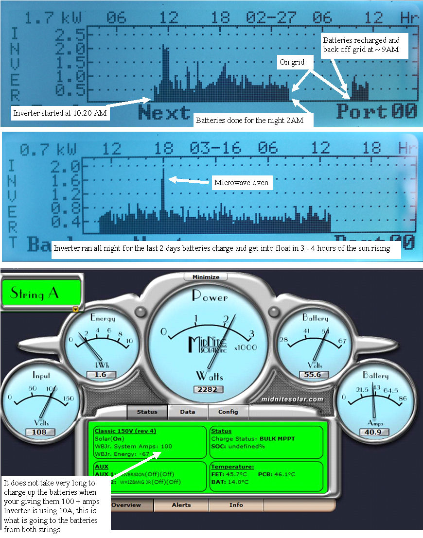 | | | Runing all day on solar |
This time of year, the days get longer, the nights are shorter, so the total time where the battery's need to power the house is just at the point where the system stays on inverter power all night, and with the huge solar array, the batteries are fully recharged by 10AM.
Nice to see the batteries make it all night.
During the day, a lot of watts are not being used, so the next stage of the project is to move the big loads to the inverter, with a way to only allow operation when the power can be replenished by the sun in real time. To allow off grid operation overnight, we don't want the 4kW water heater or 4500W electric range to operate then.
The plan is to use high power Solid State relays to enable or disable these big loads, based on the power available. The hot water heater is a load that has inherent built in storage, so does the air compressor, so when no one else needs high power during the day, we can dump heat into the tank, and the temperature will stay hot all night.
The range is a bit more tricky, as the inverter will be overloaded if both the range and the water heater are on at the same time, so the plan is to design a load management system that will divert the daytime excess energy to the hot water tank, compressed air, until they are fully charged, and to turn off those loads if the electric range or the welder need power, and to switch the electric range to the grid if Sue wants to cook after the sun goes down.I am finding out that the outback inverter data logging and monitoring system is not very powerful, unless you buy more components. You cant control the inverter or change settings without the MATE3 controller, the MATE 3 does not include a USB output unless you buy a USB card that plugs into it. They sell the card that uses a microchip USB processor for $75, which is using $3 worth of components.
Then you find that the battery monitoring requires a Flexnet DC computer ($275) and additional shunt ($25) to give you the net Amp hours in and out so you can better understand your battery condition. Then you find that to use the Mate3 and the flexnet dc computers, you need a custom network router for another $150, when a better design could have given you all of this in the inverter and Mate3.
Well at this point, I don't have a lot of options, and with those components, I can write a labview data logger and control program that will tie together all the Misc parts. Why is it never easy!
(Posted 3/17/2014 by mikey) |
Beating on the system/ use it or loose it | 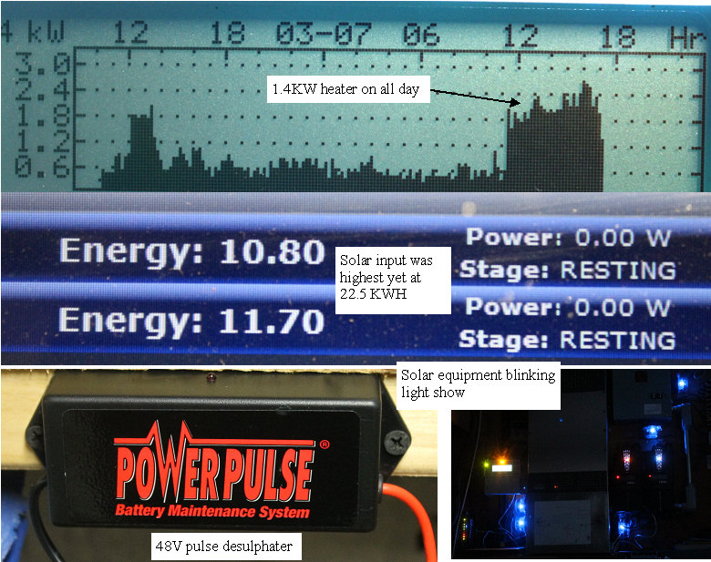 | | | making it all work harder |
Today was a nice day, and the batteries made it all night for the first time, so I decided to test the system by pushing it a bit. I set up a 1.5KW electric heater, and let it heat the solar/battery room all day. Unfortunately I forgot to turn off the heater and the batteries started discharging before I turned the heater off, the batteries were not fully charged, so I will not make it all night tonight.
The room and equipment got up to over 90F
The fans were running, but the internal temps all stayed in a comfortable zone.
The inverter is 8KW, and we were only at 2.5, so things better be ok.
The more precise hydrometer readings have confirmed that the batteries are in fact looking sulphated, so I got a High frequency pulse desulphater rated for 48V, and connected it.Should begin to see the capacity and specific gravity's improving if the thing really works.
It runs on the 48V, so it does not need a power cord.
Will have to put a scope on the batteries to see what the pulsing looks like.
The final task of connecting the big loads is next.
The issue here is that while the inverter can easily handle any of the big loads alone, it would have issues if two or more turned on at the same time. It is also important to only use the big loads when the sun is out, and the panels can supply most of the energy, as my rather small battery bank at this time of year can not even make it all night.
As the days get longer, and the nights get shorter,and I reduce my night time loads. I will reach a point where the batteries and solar get me 24 hours of off grid.
I am thinking that powering the big loads each with a big solid state relay, would let me design a big load management computer.
The energy sinks for the excess production would be the Air compressor, Hot water heater, electric heat pump, and finally the electric hot air furnace.
The on demand loads would be the electric range,machine shop , welding equipment which should be able to run whenever it is turned on, which means I will need to make sure to use the shop equipment one load at a time.
The load management system would need to know when an appliance is turned on, and then the actual application of power would be processed by the management computer, which would turn on the solid state relay and the load.
Each load would be assigned a priority. and when none of the on demand loads are on, the excess energy would make hot water, compressed air, or electric heat.
At night, the big loads would be turned off, and the energy stored as compressed air, hot water, or energy stored in the house as heat would carry until the next day, so the batteries will last all night. The highest priority will be to recharge the batteries, then when the charge controller goes into float, and turns on the Aux relay to divert the excess energy where it does the most good.
The fun is just beginning.
(Posted 3/7/2014 by mikey) |
Better Specific gravity instrument | 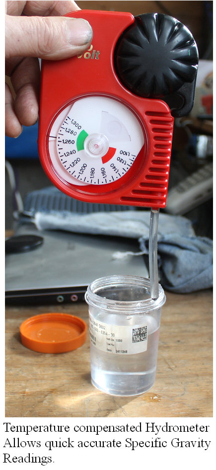 | | | HydroVolt Specific Gravity meter |
Finally got the HydroVolt temperature compensated Specific gravity meter.
The design is elegant in its simplicity.
The black bulb is squeezed, the acid is slowly drawn into the unit to completely fill the chamber. The temperature wheel and the SG wheel rotate based on the SG of the acid, and the temperature of the acid.
The SG pointer then points at the corrected value of SG.
The photo shows the device reading my acid reference solution which has a SG of 1.265.The temperature was ~ 40 F, yet the instrument gives the correct SG
Nice instrument
Hydrovolt
(Posted 3/2/2014 by mikey) |
The snow is returning??? | 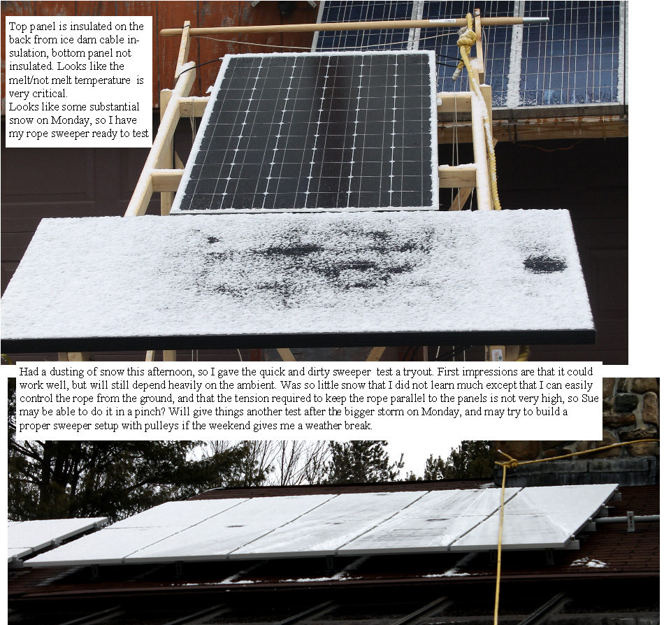 | | | ready for some snow |
Weather is predicting a fair snow fall on Monday, so I will be able to test the sweeper, and the larger heater when that is finished. I used the chimney as a quick and dirty place to attach the big rope. While this will not allow the full test of concept, it will give me some real world experience. Last week I wanted the snow to stop, now I can't wait for it to snow again,fickle human that I am.
Update**
The snow missed us completely, so no test was possible. Will leave things set up, and hope for at least one more snowfall before spring.
(Posted 2/27/2014 by mikey) |
Looking the data | 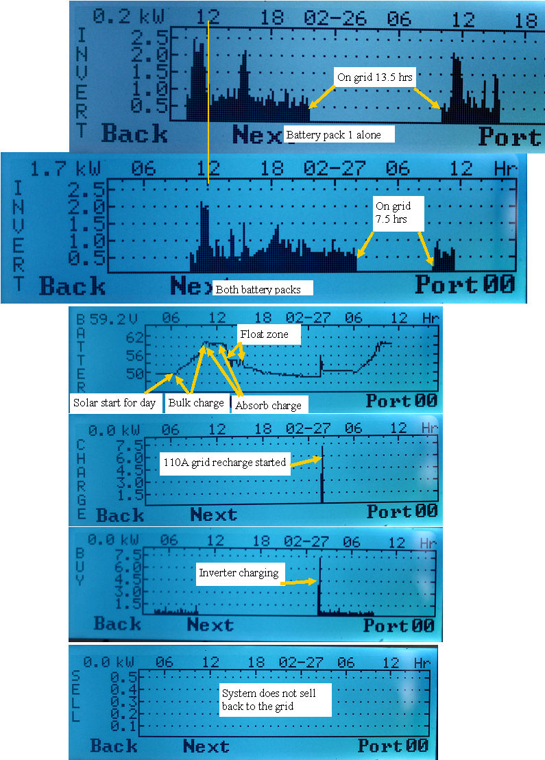 | | | looking at the difference that the second pack brings |
The inverter has a decent datalog display that lets us see what happened for the last 24 hours. When I ran the system with the single pack, I had a 13.5 hour period where the batteries had run out, and I needed to run on grid.
After installing the second pack, this on grid zone shortened to 7.5 hours. Looks like I could make it off grid all night if I had another 220 Ah, or I need to reduce the average load during the night.
Will look into using the hot water tank and the freezer as short term storage devices, so I can get the freezer colder than necessary during the sunny days, as well as heating the hot water to higher temp than needed to store additional energy when it is most available, and to extend my off grid time by moving those loads to when the power is available.
The midnight classics have an output for when the batteries have been fully recharged, which could enable running the bigger loads only when the solar is overproducting.
(Posted 2/27/2014 by mikey) |
Connecting battery bank #2 | 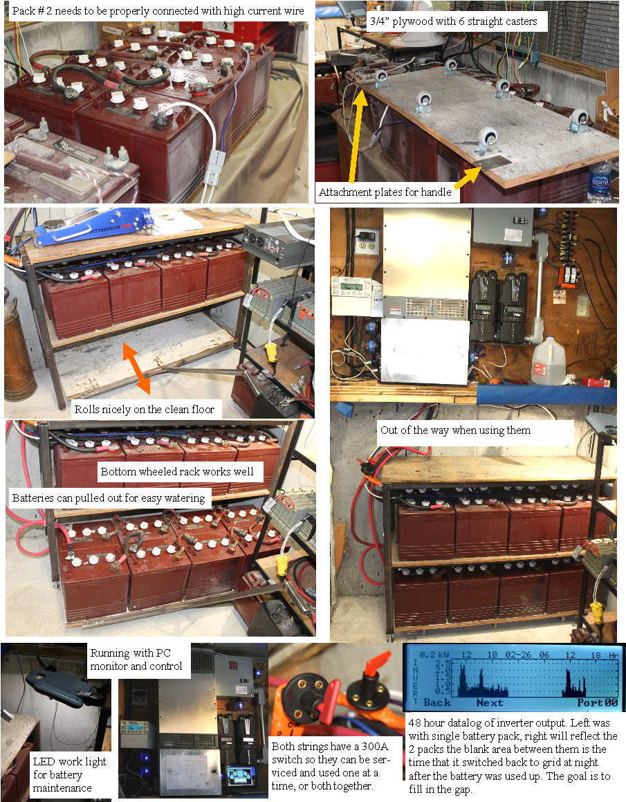 | | | installing battery bank #2 |
I had built a nice steel rack for my trojan T105 batteries so I could keep them active during winter. Now that rack will hold my solar batteries. Unfortunately getting access to the second set of batteries is a necessary and frequent function, so After considering many options, the simplest was to build a rolling base for the bottom batteries. My original stand only allowed adiquate clearance for the batteries, so the additional height of the base made things a bit close for comfort. I had welded on 1/2" thick steel bases for the stand, and had some short elevator bolts, so all it took to raise the stand was a floor jack, and some longer elevator bolts. Wired up the batteries and connected them to the inverter. I have shut off switches in each battery string so I can swap active packs or use them in parallel.
The roll out base has two steel bosses that the welded handle plugs into.
Bank 2 had sat for 4-5 days, so I charged it separately until it matched the voltage of Bank 1, and then put them in parallel.
Not much time to top them off, so it will be interesting to see how much longer the battery's can run the house.
I still have the big loads of the hot water, electric range, and the whole workshop to connect, but those loads may be able to be timed, and adjusted so they happen only when the sun is out and can supply the inverter all the juice it needs.Lots of fun tinkering to get it tuned up.
(Posted 2/26/2014 by mikey) |
Very interesting heating element | 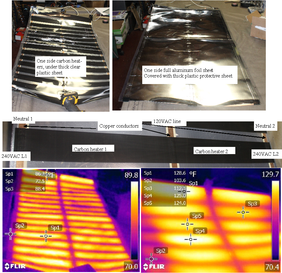 | | | Nice heating pad |
When pursuing the thermal snow melt possibilities, I contacted the Calorique company.
They make an interesting series of flat heaters, that are used for radiant heat, snow and ice melting,and some industrial heating.
I got the sample of the material today, and was pleasantly pleased by what I saw. The heater elements are dense carbon strips about 2" wide.
The 24.5" wide material has 3 copper bands, one on each edge, and one down the center.
The heaters can run on 240 VAC,by connecting the power at the two extremes, or 120VAC where the two extreme ends are connected to neutral, and the center to the 120V line.
The materials are sandwiched in a multi layer stack, with tough plastic between the layers. One side has an aluminum layer to act as a heat spreader, but one can see clearly where the heating elements are located when viewing the panel in IR.
I will install the heater on the top solar panel on my test rig, and give it a shot if we get more snow.
It looks like each 2" carbon strip within the heater can be cut off, and it becomes a 20 W 120/240VAC heater, so one could just unroll the length you want, cut it off, and make the AC connections.
The IR image on the left was after 2 minutes of being plugged in, and the one on the right was after ~ 30 minutes showing that the panel was at equilibration with the room ambient temperature and was no longer rising. Of course if adhered to the solar panel, the solar panel mass would determine the final temperature and rate of heating.
Very Cool product, (think lithium pack heater) They make variations for many applications, with more or less watt/ sq foot. Next thing is to find out how much it cost.
It will take 175 Linear feet to cover all the panels, and 12.5KW to power them all.
If my rope sweeper works, that will be the preferred solution
(Posted 2/25/2014 by mikey) |
Mikey's solar panel snow sweeper | 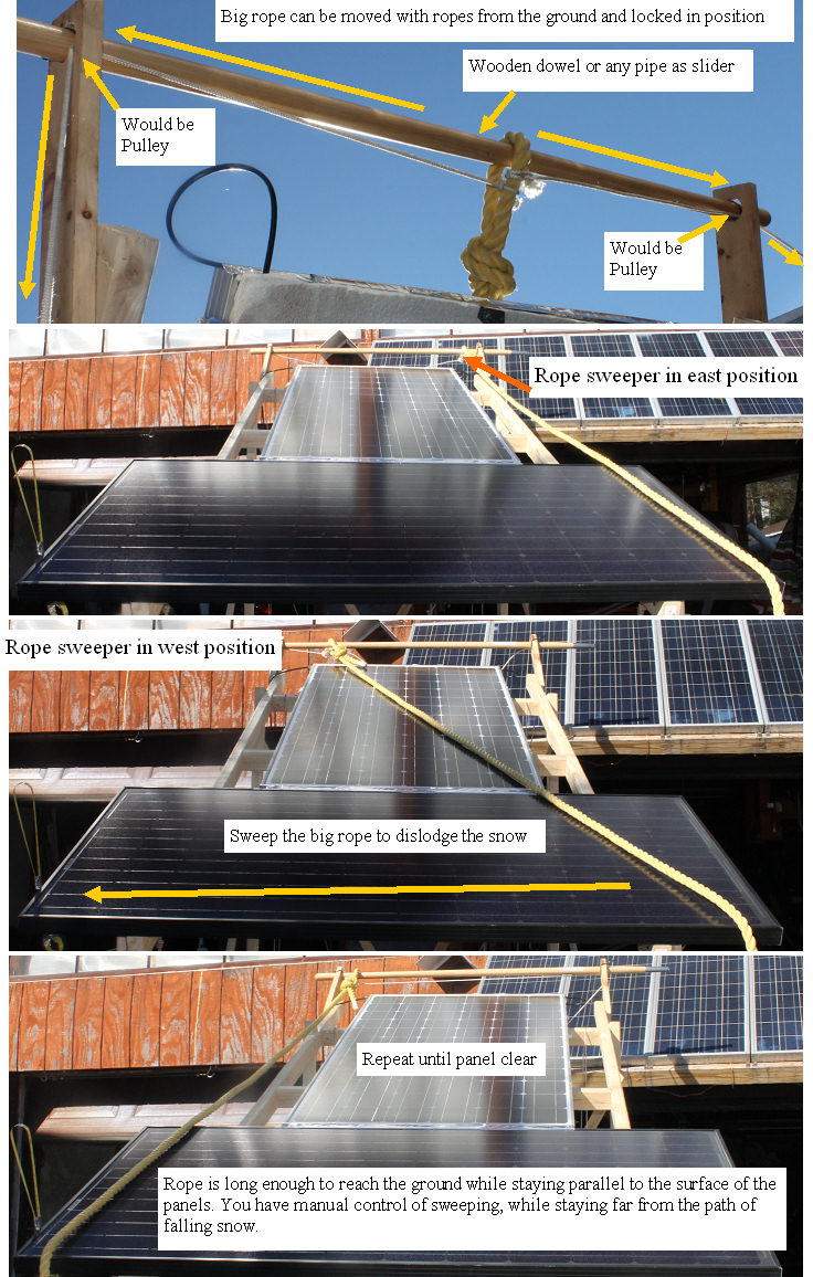 | | | Mikeys snow sweeper |
Time to go back to a more mechanical way to clear the snow.
After beating on some snow drifts with various things, I came up with a pretty simple to make,low cost and potentially useful way to get snow to slide off the panels.The same system could also clear roofs.
In all the test i have did to date trying to melt the snow,I found that all that is required to fully clear a panel is to give the snow a nudge, and then the snow just slides off with gravity's help.
A bar, pipe, dowel is supported above the panels.This needs to be rigidly attached so you can pull as hard as necessary to get the snow moving. A 3/4" diameter poly rope is attached loosely with a loop. The loop can be pulled left or right with a smaller diameter rope, which would pass through pulleys on the left and right ends. By pulling on the small ropes, you can slide the loop anywhere along the bar, and hold it there if the ropes are tied down.
To clear snow, you would pull on the big poly rope end on the ground, far enough from the building to put the rope parallel to the panels surface. Then you just pull and sweep the rope across the surface to clear the snow.
This means I would have to snow blow a path at the right distance from the house to get the angle right, but that is not as difficult or dangerous as getting on the roof.
The top can be moved left or right to sweep multiple times, all far from the house, away from falling snow.A small cleat to tie down the two small ropes would lock the top loop in position.
Would work best the morning after the storm, when the snow is fresh. Leave the ropes set up all winter, and put a top slide across all of the house peaks to allow clearing either side of the roof with the same bar and separate ropes. Sounds good on paper, the real test will come when it snows again.
The same rope can be used to support the end of a very long snow rake.Imagine a pulley that the rope runs through right above the rake. The rope is held in one hand, the snow rake handle in the other. Lift the rope to get the snow rake end over the snow, push the rake up to get another bite of snow, pull down the snow. I hope that the rake would only be required if the snow is too much for the rope alone. I also rigged up another poly rope tied to the base of my chimney over the panels and to the ground, so I can test clearing a limited sweep of the real panels to see how it works. Now all I need to try it out is another snow storm.
(Posted 2/22/2014 by mikey) |
Concentrate the heat test #4 | 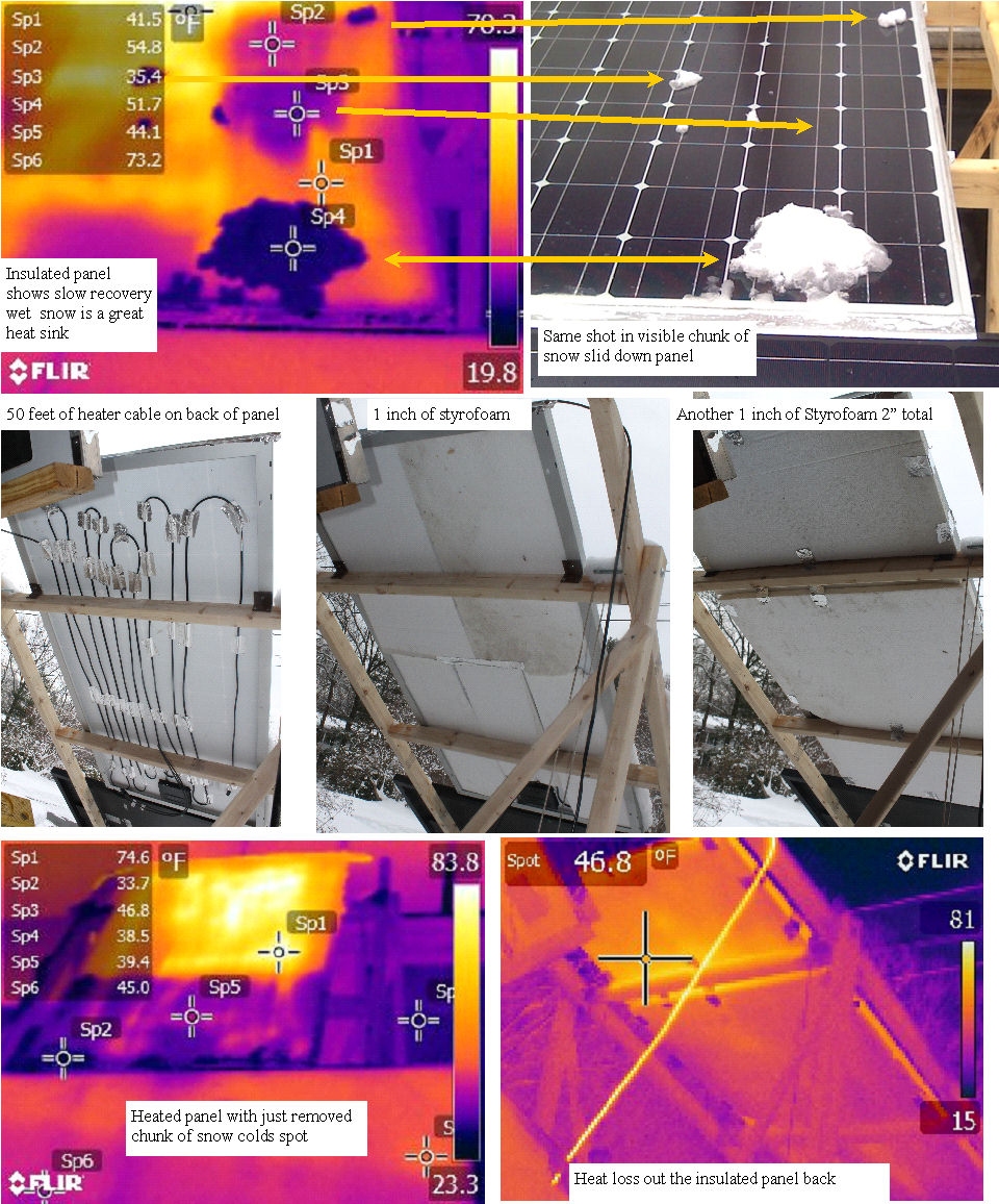 | | | maximizing the heat |
I removed the 60 feet of cable, and re routed it to fill the back of the upper panel.
The cable dissipates 270W, so I figure I have at least 200W under there.
To reduce the heat loss out the back, I put two layers of 1" thick Styrofoam.
The snow melted to slush and then flowed away as water, but the wet heavy snow did not simply slide off in a chunk as hoped. I put a big handfull of snow on the heated panel. It slid about 4 inches, and sat for 5 minutes before sliding to the bottom lip.
In all I ran the heater for 1 hour, and only mostly melted a 3" X 14" X 12" area
Need to get the snow to slide off instead of trying to fully melt it.
It looks like the panels surface has quite a bit of friction at my 26.5 degrees when the snow is very heavy and wet. Will try some rainx to see if the snow slides better on that.
Did some further test and found that if the panel is heated to over 100F, that a hand full of snow will melt immediately and slide right off, due to the thermal mass of the heated panel. With snow on the panel when the heaters are turned on,a much higher wattage would be required, and that will not be a practical, reliable, or economical approach to clearing the panels. A mechanical system may be the best overall solution, as once the sun hits the cleared panel, it will melt off the small amount of snow that remains.
(Posted 2/19/2014 by mikey) |
Not very encouraging test # 3 | 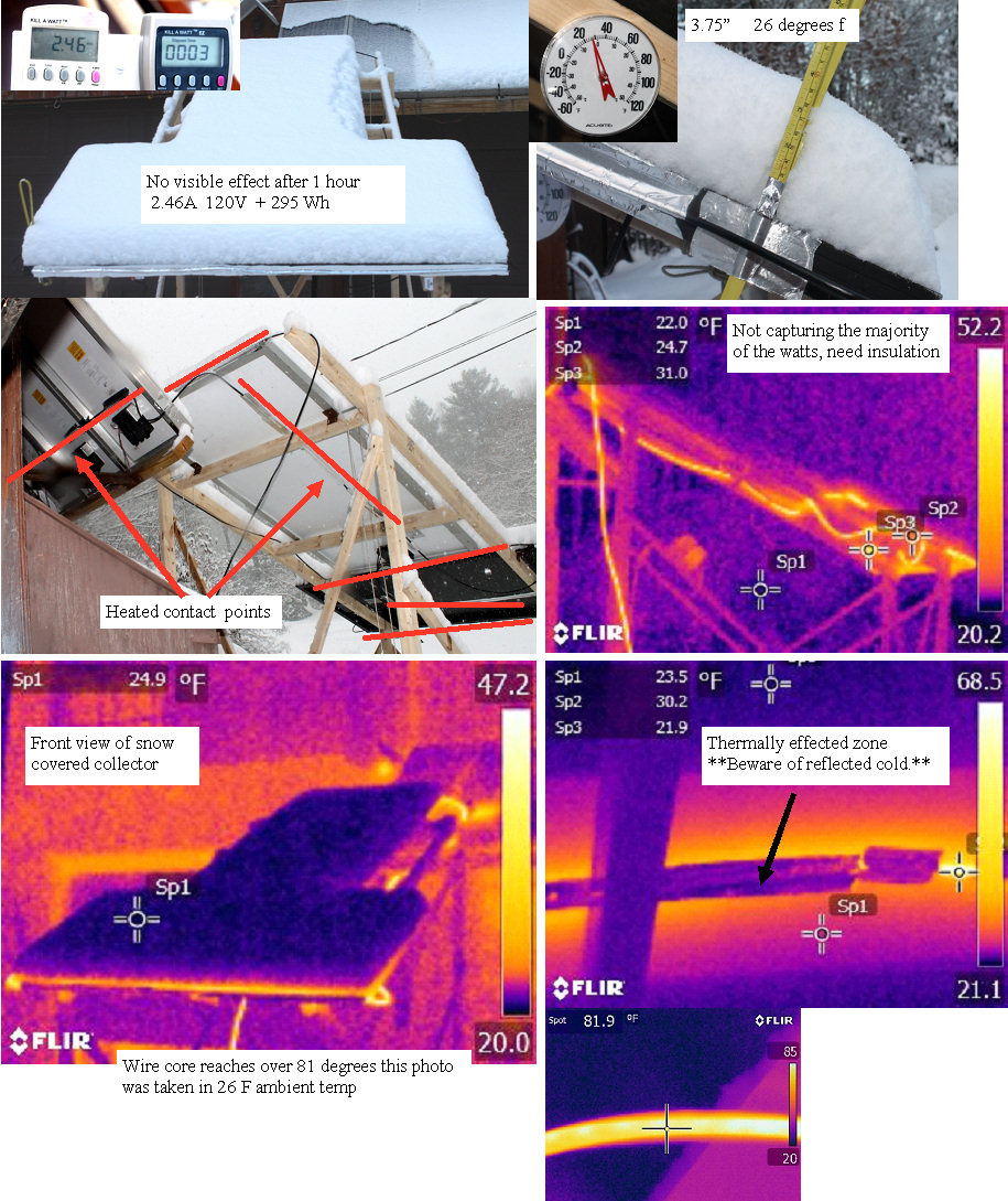 | | | looking at the results |
The snow ended at ~4PM, so I went out and turned on the heater. Nothing happened, and the IR image shows how much heat we lost. Will try re routing the cable for tighter coil spacing to see if I can get all of the heating tape on the two panels, and add some insulation to use it all for heating the surface instead of wasting it.
Will need to use some black tape or cloth duct tape over the foil covered wire to avoid seeing the cold snow reflected off the foil. aluminum is a great reflector for IR as are copper and gold.
Found this info:
Class 1 systems allow a layer of snow to accumulate during a heavy snowfall and then melt the snow over a several hour interval after the snowfall stops or slows down. These systems typically deliver 80 to 125 Btuh/sq ft (23 to 36 watts/sq ft) depending on the location.
looks like I need more concentrated heat.The Calorique panel they are sending is in the 50- 75 watts/sq ft range. I will use a variac to crank it up gradually.
(Posted 2/18/2014 by mikey) |
Snow melt prep for test 2 | 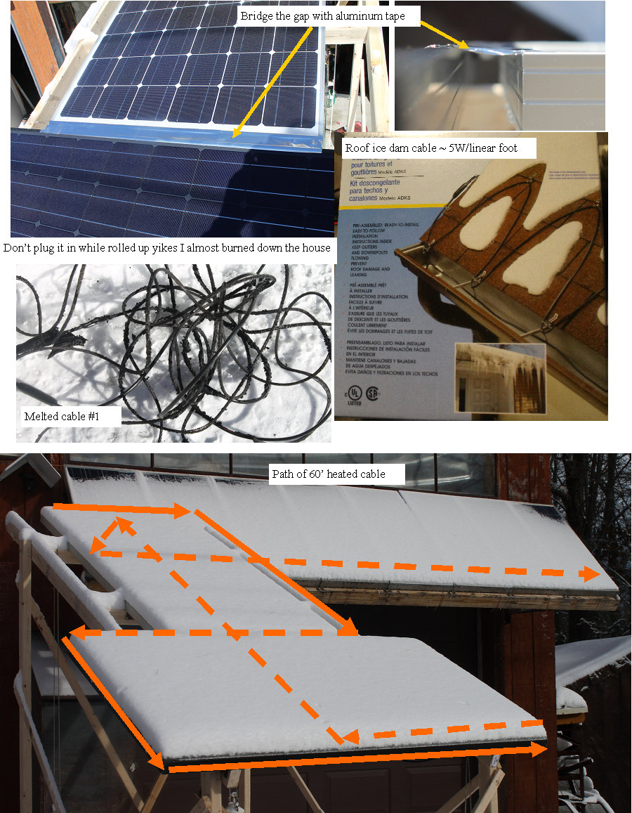 | | | getting ready for test #2 |
After the panels cleared and dried, I bridged the gap with some 3" aluminum tape, and bought a 60 foot roll of the 5W/linear foot ice dam heating wire.
I set it on my pool table still coiled up, and plugged it in so I could use the thermal camera to watch the warm up.
On the way to the camera, the phone rang, and I found my self in a conversation about battery charging. About 10 minutes into the conversation, My eyes started burning, and I could not breathe. I looked over at the coil of heater wire, and saw a plume of smoke rising. Put on some gloves, unplugged the now totally melted coil of wire, and threw it into the snowbank out back.
Like most engineering types, I had not read the manual, where it clearly states that plugging it in coiled up was not advised. Well that was a $45 lesson I will not forget soon.
With yet another 3-7" of snow predicted for tomorrow, I could not waste a good test opportunity, so I went back to Lowes, and bought another 60' coil.
I installed the wire by taping it to the panels with aluminum tape, in the pattern shown, and will plug it in when the storm ends, and carefully watch what happens.
I also contacted a local company
Calorique
that makes many types of heaters for snow melting, and they graciously agreed to send me a heating pad that I can apply to the rear of the panels so I could give that a try.Now we just wait for the snow to stop again.
(Posted 2/18/2014 by mikey) |
Snow melt test one A close look at the process | 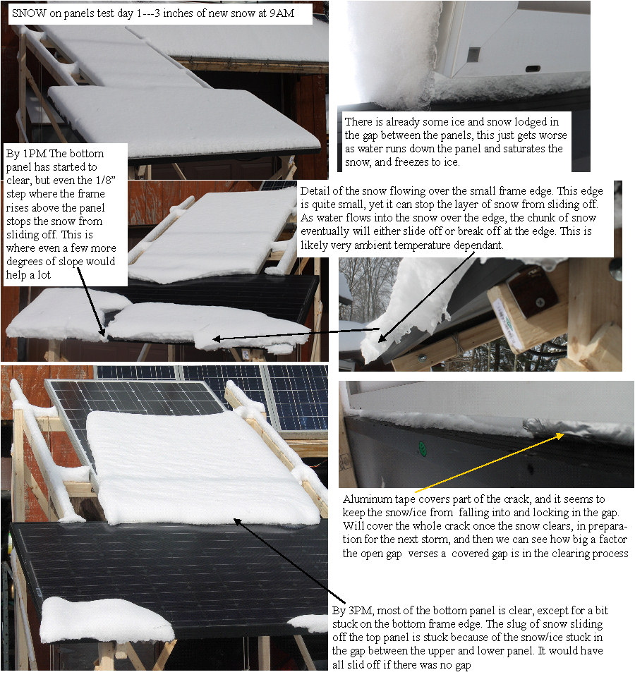 | | | Snow on panels TEST 1 |
We got about 3 inches of fresh snow on my test panels last night.
It is clear that even the tiny ridge where the panel frame is higher than the panel surface is a big obstacle to the snow just sliding off. As the snow melts, the moisture sinks down to the base of the snow, right on the panel, and slush develops. The slush gets caught on the small lip, and will not allow the snow to slide off at my rather shallow slope. No doubt this would be a much smaller problem at steeper pitches, and the slush would be more slippery if things were just a bit higher in temp.
The gap between panels seems to be the major catching area, as the snow/slush flowing from the top panel just falls into the gap and gets more and more saturated, as well as filling the gap deeper and deeper.It was in the 20s today, so the slush was just at the freezing point. The snow above because of the shallow slope does not have enough force to break off at the gap and just slide off, so the snow will remain until the slug in the gap breaks off or melts.
First thoughts are that covering the gap with aluminum tape, and maybe running an icedam heating strip between the panels horizontally would prevent this?
Will modify the test setup and be ready for the next storm.
(Posted 2/16/2014 by mikey) |
The snow keeps on coming, need to figure out a good way to keep the panels clear | 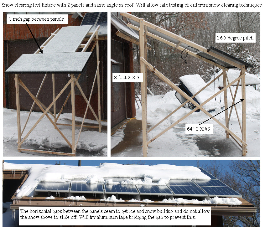 | | | snow removal test fixture #1 |
And were getting another snow storm. If this is an example of how winters will be from now on, figuring out a system for keeping the panels clear is looking like a necessary investment in time and some experiments.
The problems with this seemingly simple task, is the wide range of variables involved.
I once heard that the Eskimo language has over 100 words for the different kinds of snow, and I am beginning to see why.
So far I have observed several things
1. if the temperature of the panels gets to slightly over 32, the panels will clear them self.
2. if the sun can hit the black panel surface, the melting will proceed nicely if the ambient temperatures allow the panel to raise above the 32 degrees, but if it is colder than 20F,even full sun on the panel will not be able to get the panel warm enough.
3. if snow remains on the panel, for a couple of sunny days, the water melting off the panels will saturate the snow bridging the 1" horizontal gap, and can freeze (like an Icicle) and then the ice forms a dam that holds the snow which needs to fully melt before the melting snow above can slide off
4. wet snow that freezes on the panel with the temps staying low will stick strongly to the panel surface, lite fluffy snow will easily blow off the panels.
Summary
The moisture content of the snow, the ambient temperatures as well as full sun or not are all strong variables that will effect the panels clearing.
Possible approaches and considerations:
A mechanical snow sweeper would have to run during the storm to prevent the buildup of snow.
Expecting a sweeper to move 5-12 inches of snow that has frozen to the panel surface would likely stress any reasonable mechanism.
Warming the panels and covering the gaps to allow the snow to slide off on its own may be the best approach. The issue then is how to get the heat to the panels and how to get the heat without it requiring more energy that is lost due to the lost electricity from the PV.
Playing with the real panels on the roof is way too dangerous, so I built a simple test fixture with my two spare panels so I can experiment safely while we are still in the deep of winter.
Changes to the jet stream due to climate change will likely make this type of winter more common, so it is something that needs to be looked at. Ice dams and roof over stressing due to the heavy snow load are also of concern.
(Posted 2/15/2014 by mikey) |
Yuck, more snow | 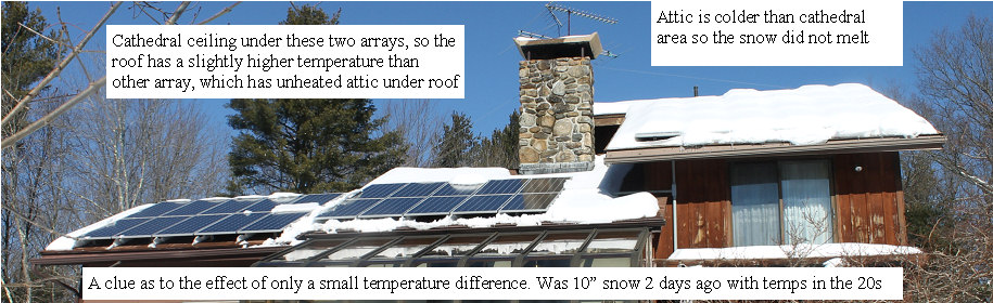 | | | need a litttle heat |
Here we go again, we got ~10" of the white stuff, and the temps have been in the high 20'sduringthe day, and into the single numbers at night.
Noticed that the two left most arrays that are above a cathedral ceiling (think more heat loss), have nicely cleared them self, while the larger array on the right which is over the unheated attic, has hardly cleared it self at all.
Looks like the ambient temp + a bit of heat can make a huge difference in the self clearing of the panels.
Bet if I made some solar air heaters that were vertical at the base of the PV arrays, that the rising hot air could really help get the snow melting going. Would just dump the heat in the summer. May rig up a quick test if I can find some appropriate material
(Posted 2/7/2014 by mikey) |
Reading Specific Gravity accurately | 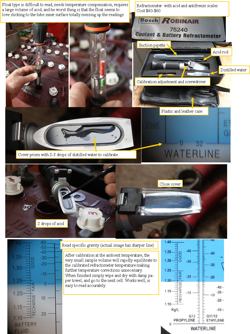 | | | Getting accurate readings of Specific Gravity |
After struggling trying to use a float type hydrometer for testing the Battery Acid specific gravity and giving up from frustration due to the float always sticking to the side and not reflecting the true sg, I got a Reflectometer type. What a difference. In less than the time I tried to get 2-3 readings with the float, I accurately measured all 24 cells, and to confirm the accuracy, I repeated the test on the same cell several times and got exactly the same reading on all test. My advise, don't fool with the float or floating ball chepo units and get one of these if you really want to know what your batteries Specific gravity is.
Now I can proceed to determine when my equilization and reconditioning of my batteries is truly as good as possible.
I found that the refractometer is not totally immune to the effects of temperature so I have ordered another type of hydrometer that hopefully will provide accurate repeatable temperature compensated readings.
Midnight solar/ HydroVolt hydrometer
Will do an in depth comparison of the three systems.
(Posted 1/29/2014 by mikey) |
Giving the batteries a workout |  | | | exercizing the batteries |
With the crappy weather, and the out of shape batteries, I have some work to do to get them back in shape. Today was nice and sunny, so I kicked up the charge controllers equalization voltage, and let the chargers make them boil.
When a battery gets sulphated, the voltage rises when under charge since the plates are partially insulated with sulphate. The charge controllers will pump everything they can gather from the sun into the batteries until the equalization voltage is reached, and then they throttle back the current to maintain that voltage. During this process one is supposed to look at the specific gravity and record it. When the specific gravity has peaked or risen to the correct 1.280V/cell, temperature compensated value, the battery is back in shape. My first batch of batteries from the telephone truck had a low specific gravity, and from the first run test they also have severely reduced capacity.
I also seem to have overfilled the cells as the correct level should be 1/8" below the bottom of the fill well. I had it up to the bottom, so I had diluted the acid, again reducing the specific gravity, so I need to boil off some of that water.
After struggling with what I thought was going to be a good quality Hydrometer, and finding that the float always stuck to the side of the tube, I decided that unless I wanted to try and fix that problem by modifying the thing,I should look into another way to accurately measure the specific gravity.
I ordered a refractometer from Napa, and should get it tomorrow. This actually measures the SG by looking at how the heavier acid bends or refracts light. The same device can check the SG of water glycol antifreeze, and it only cost $59.
Other more expensive devices use a resonating vibrating tube which changes frequency with specific gravity, but spending over $1000 just to measure SG seems like an overkill.Time will tell.
I finally pulled the frozen batteries from the electric yard cart, and will get them ready for equilibration after the first set is as good as it gets. The tricky part of this equalization process is that as the batteries desulphate, their voltage drops, which increases the current that the charge controllers will put into them as the charge controllers try to push the pack voltage to the target equalization voltage. To avoid overheating the cells, warping plates, and boiling the acid too vigorously, I need to watch the current and temperature, turn down the equalization target voltage as things improve. This will need to be done on the other string of batteries, and getting them both into the same shape is going to be pretty tricky. One reason they do not recommend mixing batteries of difference life histories.
Looks sunny for the next day or two, fingers crossed.
(Posted 1/28/2014 by mikey) |
Crappy luck with the weather |  | | | Winter sucks |
Since I have been trying to equalize the batteries, it has been very cold, and mostly clowdy, and has had near daily snow flurries with enough accumulation to drastically reduce the solar output. On the positive side, this has convinced me that a snow removal system would likely be worth doing, and this has now risen to the top priority once the weather starts getting warmer.
Murphy go away!
(Posted 1/26/2014 by mikey) |
Equilizing the batteries | 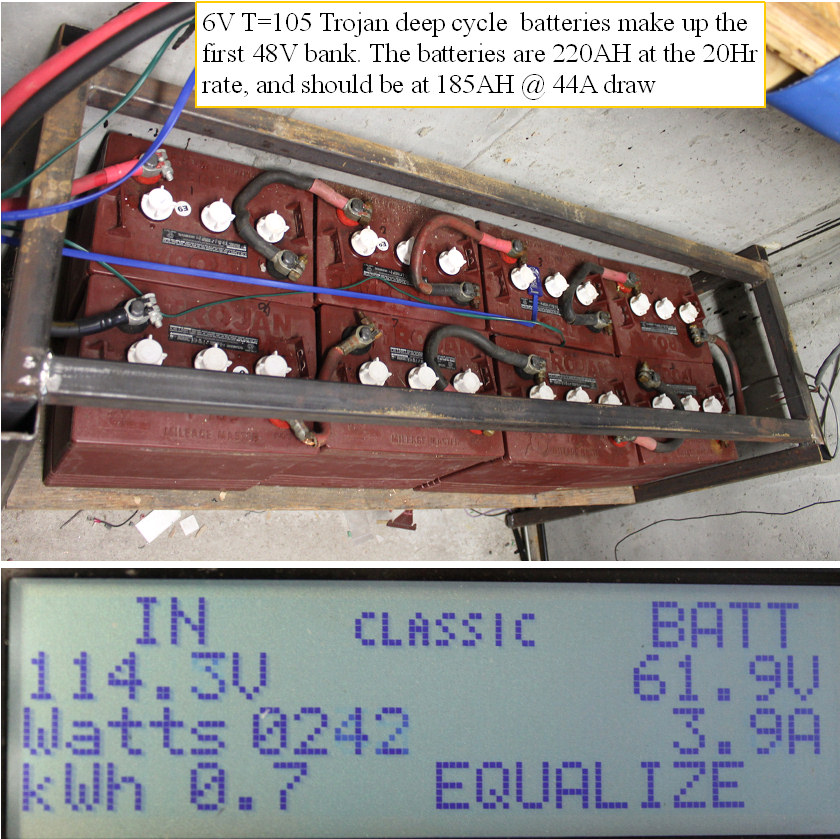 | | | Equilizing the batteries |
I got the replacement charger controller board installed, so both charge controllers are working.
Have been running some charge/equilization/ discharge cycles on the 48V bank, to get the batteries back in shape. The charge controllers will take care of properly controlling the equilization charging, and to test capacity, I set up my 1500W sine wave converter to run on the pack with no charging. I power a 1KW heater through a Kilawatt meter to discharge the pack at a pretty constant 33A. The KWH that the pack puts out before the battery drops to 48V, is a pretty good battery capacity test. Will repeat several more times to see if further capacity recovery takes place before I reconnect the whole house inverter.
First cycle got me ~ 3KWH from the pack.
It the battery was new, I should be looking at ~7.2KWH at that discharge rate.
(Posted 1/21/2014 by mikey) |
Running on batteries | 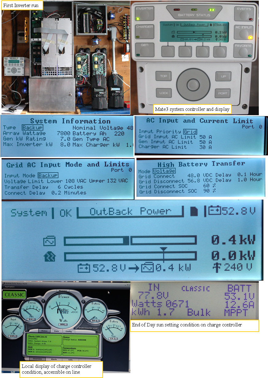 | | | first run of the Inverter |
Finally got the programming for the inverter and charge controllers set up.
One of the charge controllers would not connect to the PC for firmware update, and after determining that the problem was a bad board in the unit, Midnight solar is sending be a new board. I could have got a whole new unit, but that would involve removing the controller and wiring from the system,so I opted to wait for just the board.
The inverter is set up so it will run off the batteries as long as the battery volts are above 48V. If they drop below that value for 6 minutes, the inverter automatically switches back to the grid.
The option to recharge the batteries off the grid when the voltage drops, is there, but I opted to disable that so the solar can do all the recharging.
When the battery voltage is greater than 56.8V for a preset time, the inverter again turns off the grid, and powers the loads.
This is the first time I have tried to run the inverter off the batteries, and was very disappointed in how short the run time was.
It seems that sitting idle for most of the last 3 years in the EV bucket truck has drastically reduced the capacity. I will do some equilization charging to see if I can get them desulphated. Having a 48v 220AH battery in the EV truck that at most needs to move the truck 4 times a year, was probably not the best use of the batteries.
Think I will make up several 48V NIMH packs from the Prius subpacks and just install them with Anderson connectors when I want to use the vehicle. Will do the same with the electric buggy.
(Posted 1/18/2014 by mikey) |
Everything is working again. | 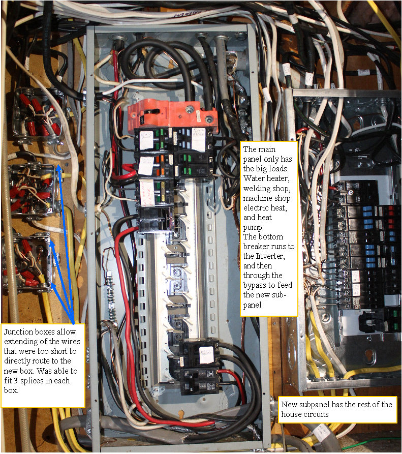 | | | finally got all my circuits working again |
The rewiring ordeal is finished. All of the house circuits have been rerouted to the subpanel except for the big loads. Eventually the machine shop and the hot water heater will be moved, but this is sufficient to get all my circuits working again, and to proceed to the final wiring and start up of the inverter and charge controllers.
Was nearly a week of work to make it happen. Murphys law, things always take a lot longer than you first think they will.
(Posted 1/5/2014 by mikey) |
Starting the rewiring | 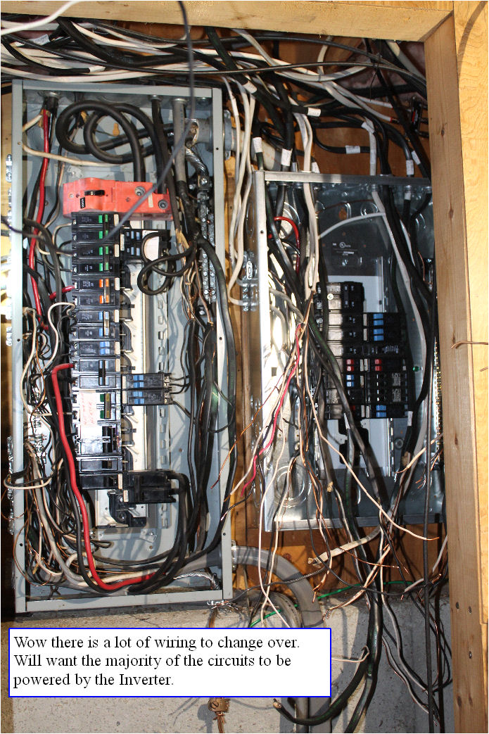 | | | lots of wires |
Got about half of the wires pulled out of the old box and moved to the new box. Much of the house is without power, except for the key circuits.
Will quit for the day, and hope to get the rest moved to the new box, and turned on tomorrow, using the Inverter bypass.
(Posted 1/2/2014 by mikey) |
Identifing the wires, and mounting the Inverter panel | 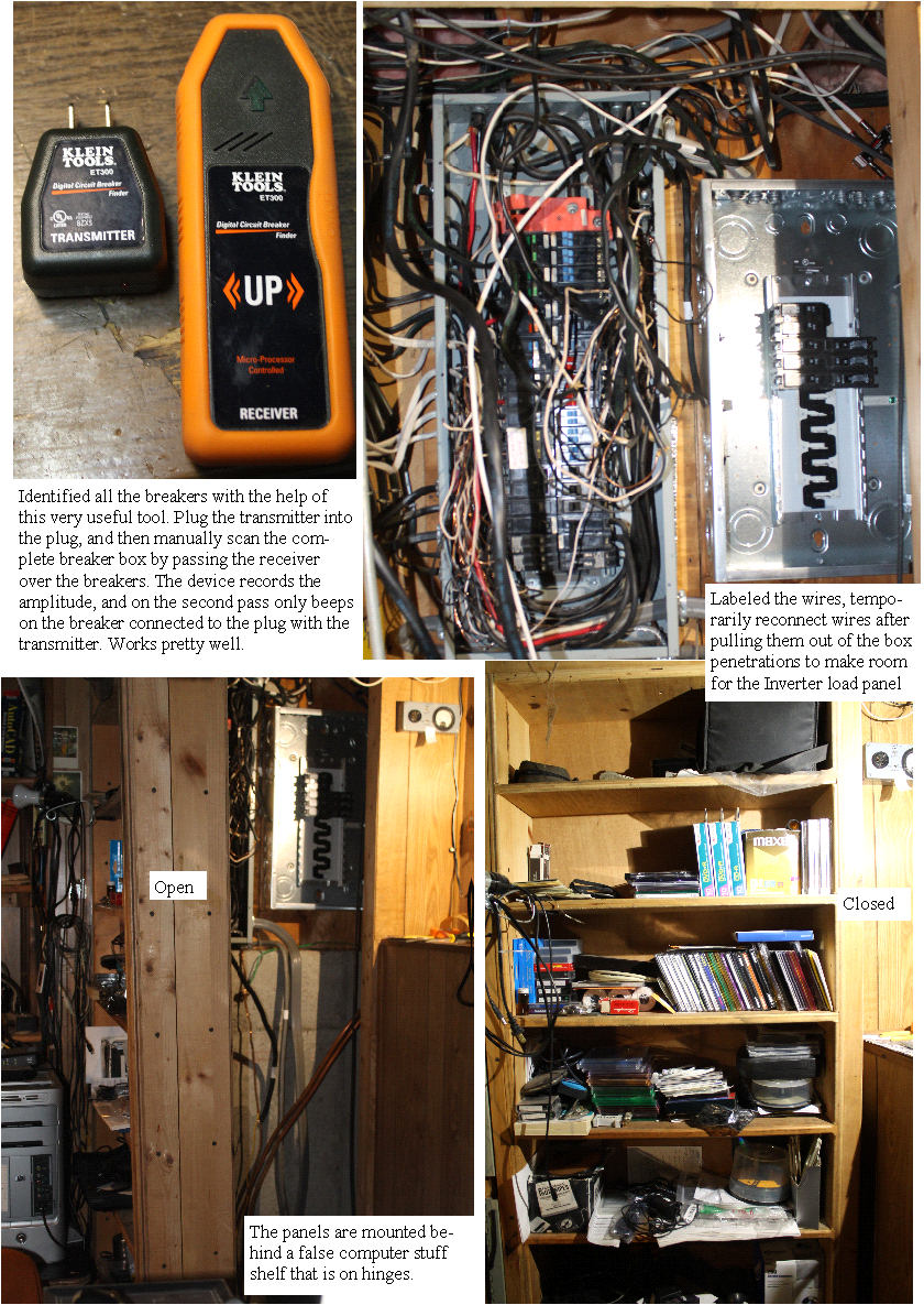 | | | mounting the Inverter breaker box |
New Years Day 2014
I used the breaker finder gadget to identify the wires and breakers so I could intelligently connect the loads I want powered by the Inverter to the new box.
Needed to do it incrementally so we don't have to be without power during the transition.
I disconnected and pulled each wire from the right side of the panel, and then reconnected it directly.
This got the bare wall exposed and allowed me to remove all the wire feed through fittings, so I could mount the new inverter breaker panel.
Tomorrow during the snow storm, I hope to get it connected so I can power everything with the bypass.
Getting closer every day.
Happy New Year All
(Posted 1/1/2014 by mikey) |
making the connection to the existing wiring | 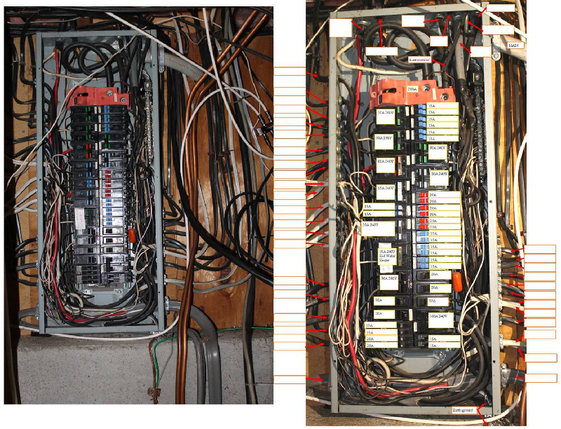 | | | Figuring out what to connect |
Now I have to deal with finding the loads that I want to run off the inverter, and moving the wires to a second 100A breaker panel. What a mess of wires!
(Posted 12/28/2013 by mikey) |
the finished load center and charge controller connections | 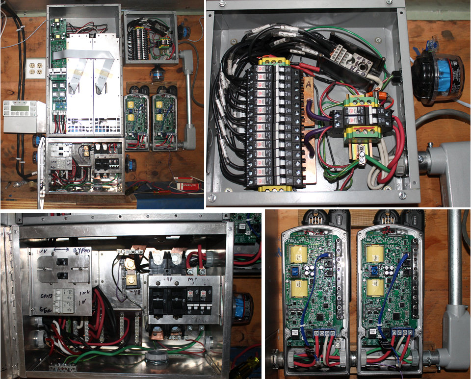 | | | final AC and charging wiring |
The final AC and bypass wiring is done, as well as the combiner box to charge controller wiring. All that is left in this part of the install is to make the high current connections to the batteries.
The AC wiring was a bit tight, but I got it all in.
(Posted 12/28/2013 by mikey) |
the final high current connections | 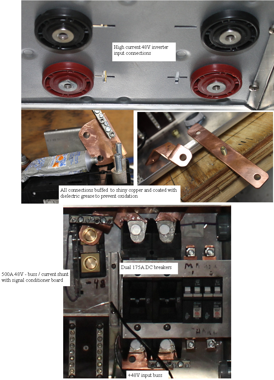 | | | final high curent buss bar prep |
My pure copper buss bars do not have the benefit of being nickle plated to prevent corrosion and oxidation, so after some research, it seems the next best thing is to buff the connections to shiny copper with steel wool, and then coat the connections with a petroleum grease like Vaseline or dielectric grease.
This material remains stable for years, and acts as a moisture barrier to keep the bare copper clean and shiny. This part of the load center is like a puzzle, and needs to be assembled in a specific order. Now I am ready to finish up the AC wiring, which is going to also need to be done in a specific order.
(Posted 12/26/2013 by mikey) |
keeping warm. | 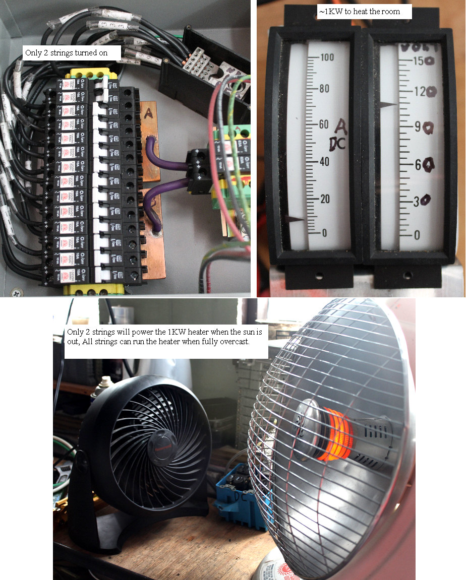 | | | keeping warm while working |
The room that the equipment is in, is not heated, so I made a simple electric heater that can run on the dc from the panels.
The 14 strings of 3 panels in series each, give me a nominal 130VDC to play with, so my 120VAC parabolic IR heater provides a nice load. I had to bypass the tilt switch,the on off switch, and the thermostat, so that the unit can safely run on the DC current. With the full sun, the 1KW heater runs nicely on just 2 of the strings as shown here.
The room is not very big, so I can easily get it to 70F in less than 1/2 hour.
(Posted 12/26/2013 by mikey) |
Almost ready to wire things up | 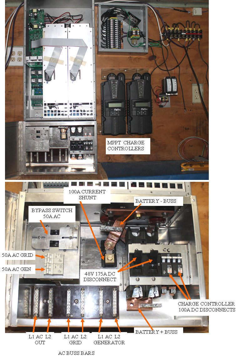 | | | almost ready for final maching then wiring |
Did some fancy fitting of components into the load center, and some tricky bending and fitting of the big 1/4" X 1.25" copper high current interconnects.
Need to identify where the box penetrations need to be, and do a final disassembly to make the holes, install pem nuts for the mounting screws, and then I can assemble the load center one last time, and then do the final wiring.
Another storm has added 8 more inches of the white stuff, so have not, and will not be making much power until things warm up.
(Posted 12/17/2013 by mikey) |
Who pulled the plug? | 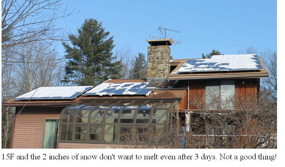 | | | Who pulled the Plug? |
We had a light snow storm of only a couple of inches, and it got very cold. The temps have not raised above 24 f for 4 days. After seeing no panel melting after a full day of sun, I took a long window washing pole and tried to clear off some of the panels to see if simply exposing the black panels would raise the temp enough to melt the rest. It helped, but as this photo shows, the only way the full array would be making power would be if it was fully cleared. Only found one German design on the web for a snow clearing system, but it is nearly as expensive as the panels, and not available here.
snow removal and washing system
I can see how for an off grid system in this climate, with a not very steep roof slope like mine, that this could be the difference between having charged batteries after a storm induced power outage or running out of battery charge even with the sun out.
Another project for my list.
Assuming that the system could be made inexpensively enough, it could be the beginning of a nice product for all the rest of the people in this type of climate with similar situations.
(Posted 12/13/2013 by mikey) |
bringing in the batteries | 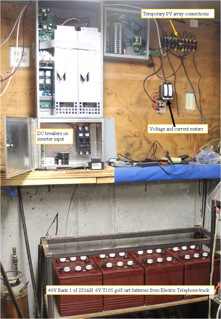 | | | bringing in the batteries |
I will start with running the system off one set of 6V T105 golf cart batteries. I usually pull the batteries from my 48V EV telephone truck, each winter, so I already have a nice heavy duty stand for them.
This will give me a 220Ah string.If I drain the pack completely, that gives me 220X48 or 10,560 Watt hours of storage.
I will probably run off the one set for a while to see how everything works, see what shape the batteries are in, and then consider bringing in the other 8 batteries from my electric yard buggy.
Together this would give a Max of 21 KWH of storage.
I will probably need more once I get off the grid, but this will give me some good experience so I can better size the final pack.
It was pretty cold today, so I connected a 1kw 120V infrared parabolic heater directly to the panels to heat the room. I bypassed the switch and thermostat so it would not burn up,when cycling (thermostat and switch would burn up if opened with dc) and managed to heat the place even though it was fully overcast.
The panels were still able to put out the 9A @ 120V to get the heater fully powered.
(Posted 12/8/2013 by mikey) |
making the DC pos buss bars | 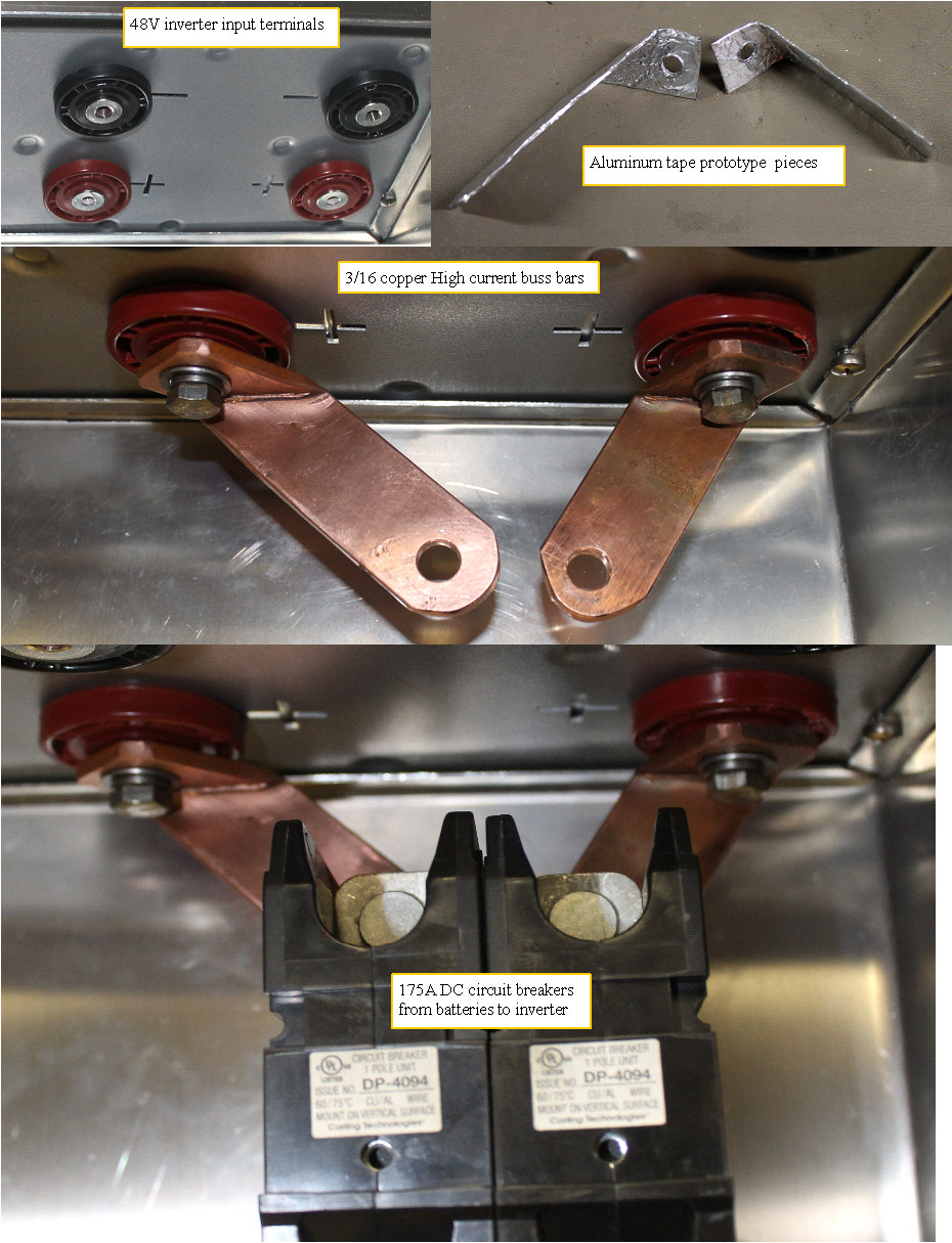 | | | Making the DC buss bars |
Now that the box is made to fit the space available, I need to mount everything inside so I can wire it all up.
The big DC input breakers look like a good place to start.
The two main positive dc buss bars need to connect from the two + terminals on the inverter, to the big 175A DC breakers. Need to allow room to tighten the screws. and the breakers want to mount together, so two complicated buss bars needed to be made.
I used the aluminum tape method to make some soft aluminum bars that I could hand form to the required shape, and then transferred that shape to the heavy copper buss bars.
I first annealed the copper by heating it red hot and quenching, so it would bend easily.
I clamped the short side in a milling machine vice, and bent it by hammering.
I brought the two pieces back into the solar room, and again checked them for proper fit.
Brought them back into the shop, and again annealed them, and tweaked them to the exact shape I was looking for.Finally I marked the exact position of the two breaker terminals, and drilled the final 2 holes.
Now that that is finished, I can mount the rest of the breakers on Din rails, and fabricate the bypass breaker assembly.
(Posted 12/8/2013 by mikey) |
power distribution box fabrication | 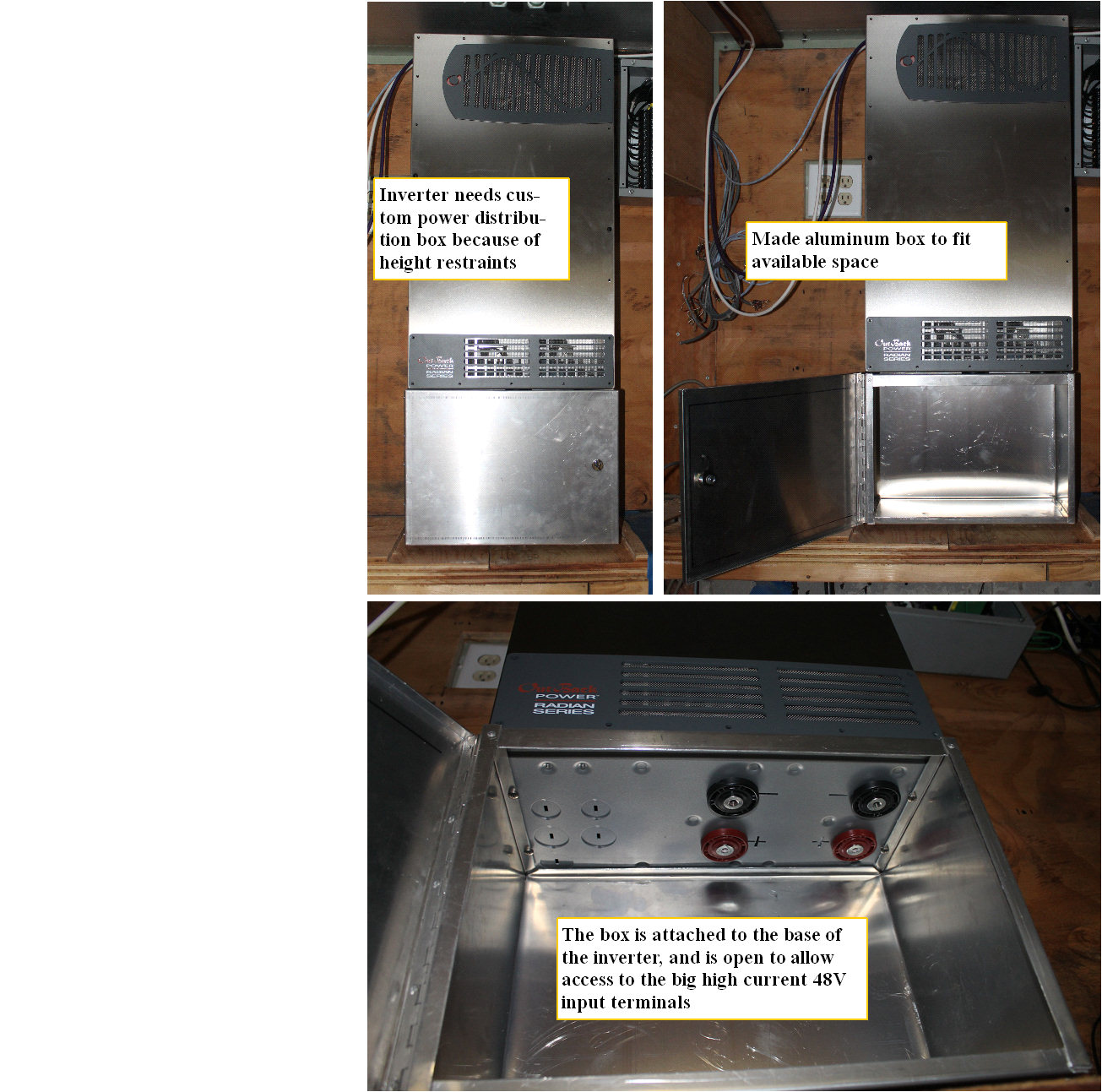 | | | custom distribution box |
The inverter will have 2 AC input circuits, one for the grid, one for a generator, one output AC circuit, the Battery input, lightning protection, all of these need to be protected in a metal distribution box.
Unfortunately the space under the inverter is too small for the distribution box that is sold for the inverter, so I made a custom aluminum box with cover that will contain all the circuit breakers and interconnect wiring.
(Posted 12/4/2013 by mikey) |
Getting started on the final wiring | 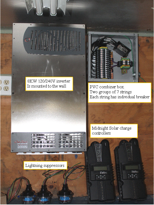 | | | starting the wiring |
While my quick and dirty PV wiring was adiquate for the playing around I did to familiarize my self with the power, It would not pass the muster of the electrical inspector, so now it is time to wire it up for real.
Scrounged in my electrical surplus, and found some parts that I could use, but had to buy the special DC circuit breakers. I put a separate breaker on each string, mostly for ease in diagnosing any issues that may crop up in the future. The 14 strings are separated into 2 groups of 7 strings so the two MPPT charge controllers can each have their own array.
The two charge controllers can each put out >80A of current into the 48V battery bank.
The 130 lb Inverter was quite a bear to get up on the hanger,but buddy Paul and I managed with the help of a hydraulic jack,and 4 hands.
The standard load center for the Inverter was too tall to fit under the inverter, so I will have to fabricate one from scratch that fits. Why is it never easy?
(Posted 12/2/2013 by mikey) |
the heavy lifters arrive | 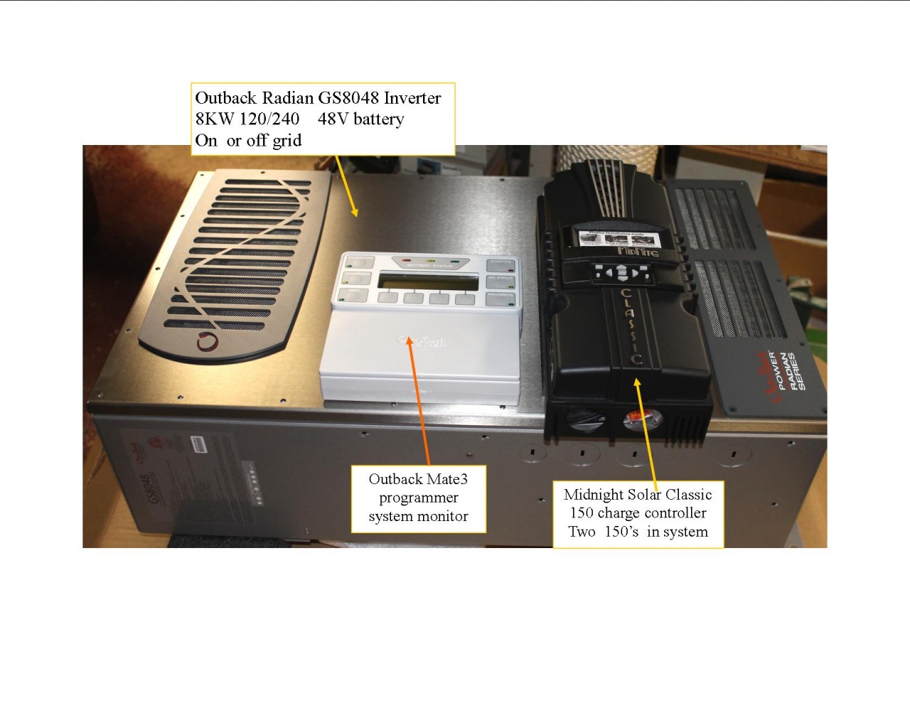 | | | the power electronics arrives |
Went to a Midnight solar seminar, at the ALT-E office in Hudson MA, and then picked up the power inverter, lightning protectors,programmer and system display, and two Midnight solar MPPT charge controllers.
Alt-E is a great source for solar components, and it has regular seminars by the major solar component manufacturers.
Now the real work starts.
(Posted 11/21/2013 by mikey) |
Getting some experience with DC | 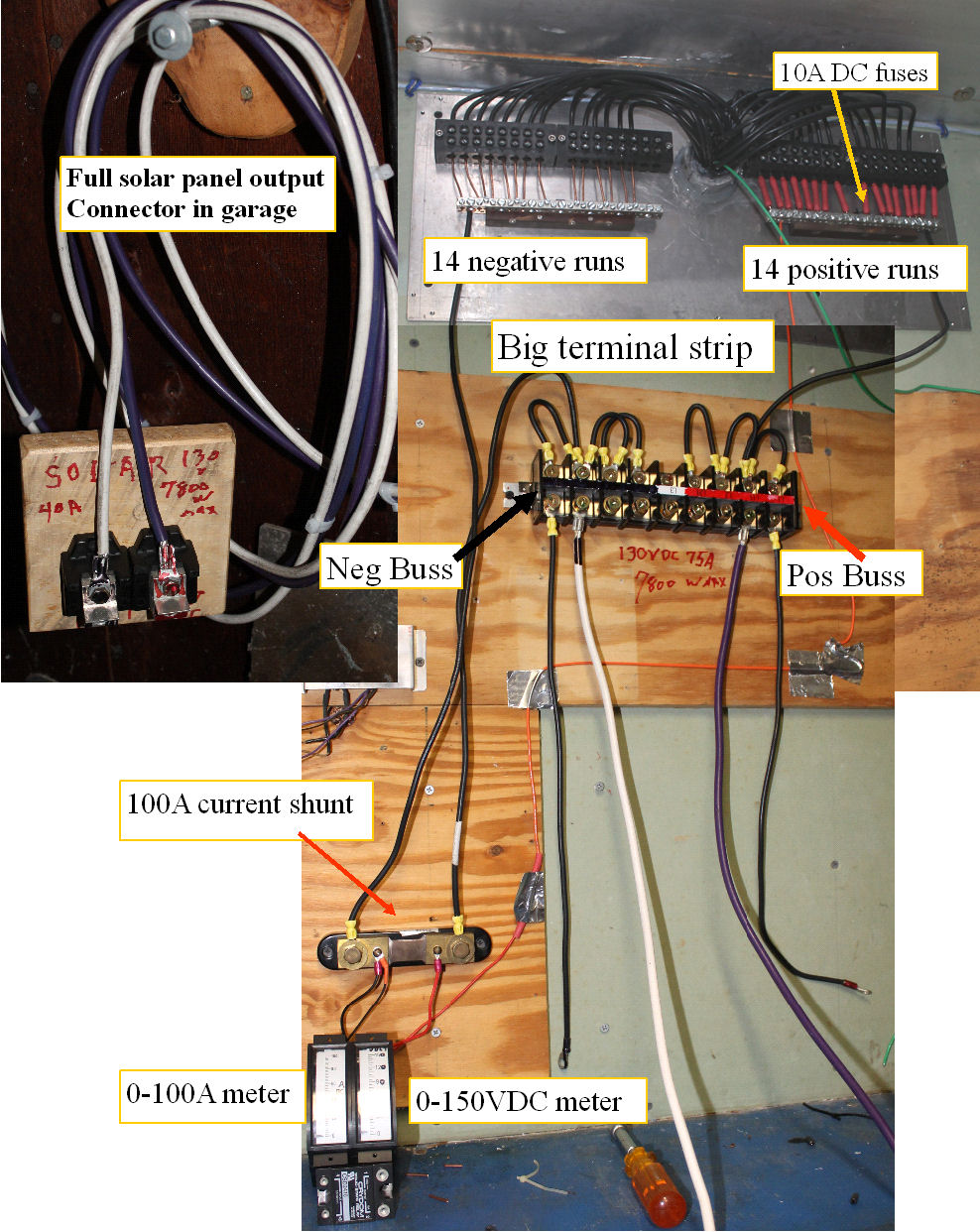 | | | making some quick and dirty test connections |
While waiting for the inverter , and charge controllers, This is the time to do some experimenting.
I set up the panels so there were 3 in series, for 108V @ the max power point, and 135 Open circuit.
In full sun, the panels are rated for 5.4A SC and 5.14A at power point.
with voltage in this range, 120V heaters will operate nicely, and two strings in series would run a 240V heater.
The only issue is the switching circuit must be able to quench the arc produced when the circuit is turned off. Same issue as the main relays in our 144v hybrid battery pack.
I will rig up some nichrome heaters that will run directly off the solar panels.
To do the experiments, I have run the full output of the system to the garage area (~ 60 feet)with # 6 wire so I can do the heater experiments where it is safe.
Want to see if I can heat the garage with the solar energy electrically.
(Posted 11/14/2013 by mikey) |
First test | 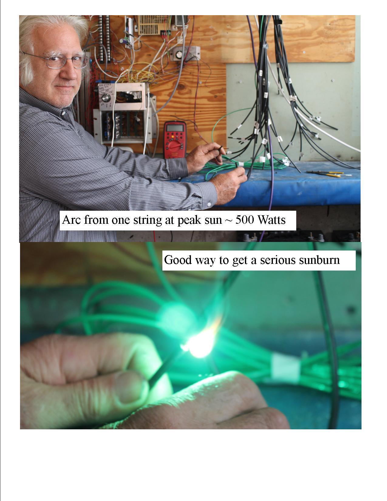 | | | First Arc test WOW! |
130VDC @ 5A will produce a hot constant arc, so each string of 3 panels was tested by drawing an arc. Bet I can weld with this. (future project)
The wires are run and all roof work is finished, so the next thing is to get the batteries,MPPT solar charge controller,and off grid inverter purchased and installed.
(Posted 10/20/2013 by mikey) |
Finally installed | 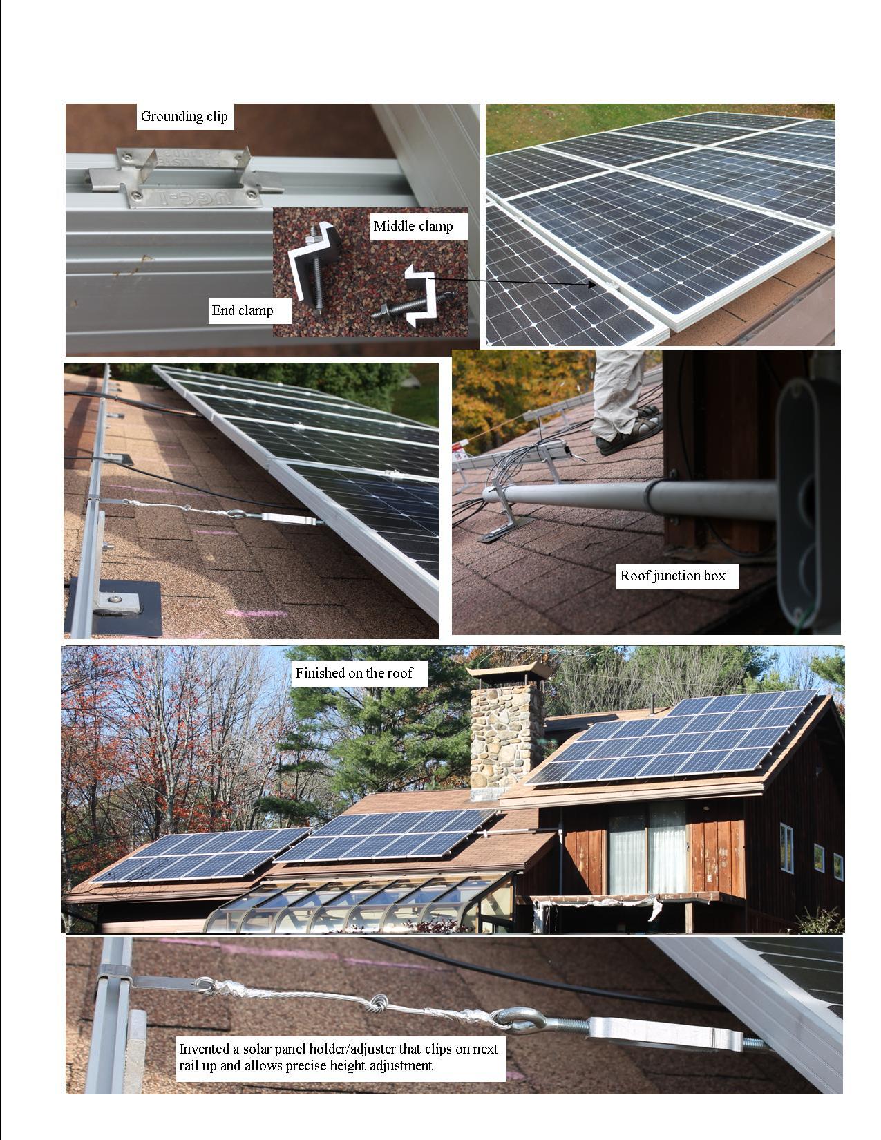 | | | finished on the roof |
Took my time and got the rest of the panels and wiring finished.
The panel frames are grounded to the rails with the ground clips. Since I was working alone, I invented a simple panel hanger with turnbuckle for precise adjustment with only one person. With this device, the install was pretty straight forward.
(Posted 10/20/2013 by mikey) |
Getting a BIG solar plug | 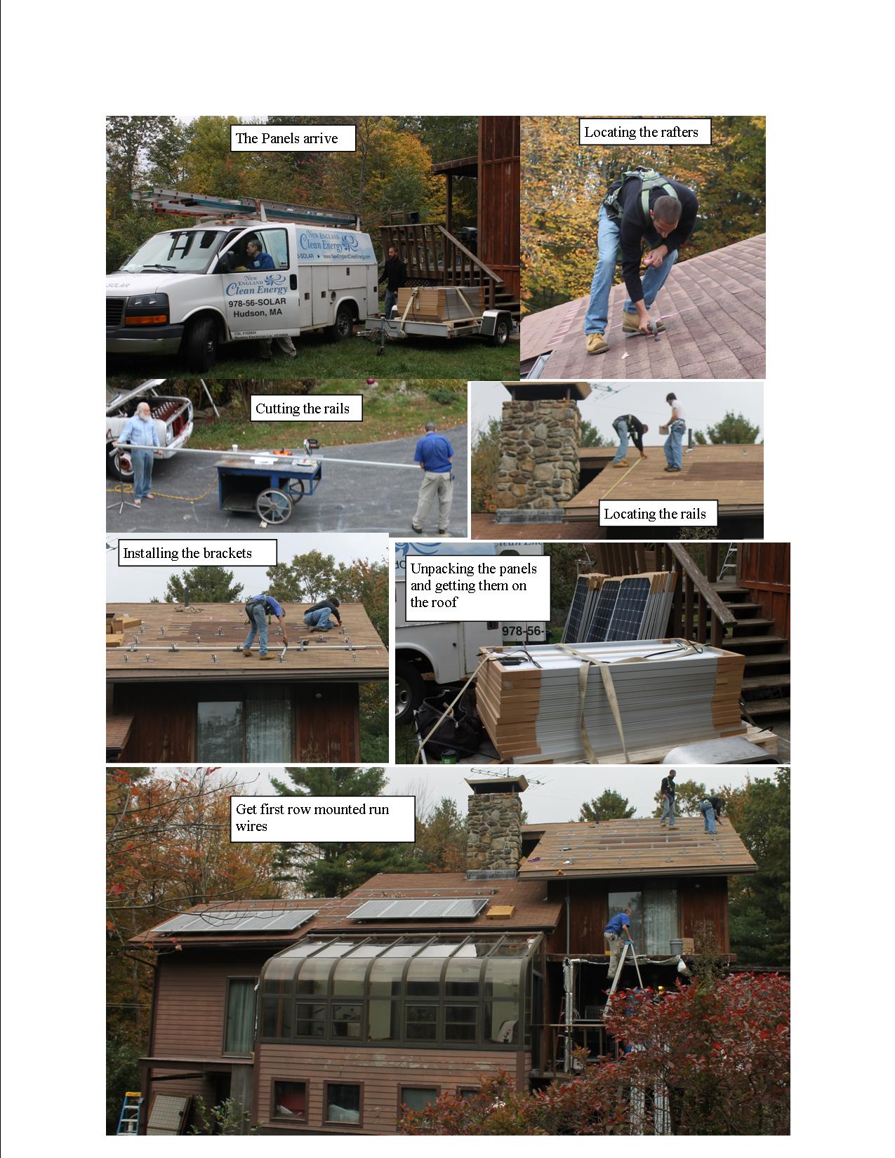 | | | getting the project started |
After saving and planing for much of my life for some serious solar PV, the big day has arrived.
My Buddy Bill from New England Clean Energy sold me some panels and the racks and guided us with the install.
Troy and Mike installed the brackets and racks, and we started the first two rows.
After looking at all my options, I decided that I would go off grid, and would design and build a flexible system that will meet most or all of my energy needs, and in the process further reduce the energy requirements for my home.
The 42 185W panels will produce a peak of 7800 watts.
Will bring down 14 150V circuits, each producing a bit over 5A.
With all the strings in parallel, that is 72A of DC at a nominal 110V @ full load.
Will use the two 48V electric yard vehicles as well as a permanent battery bank for storage.
Hope to get more panels installed tomorrow weather permitting.
(Posted 10/12/2013 by mikey) |
Making some stewed tomatoes | 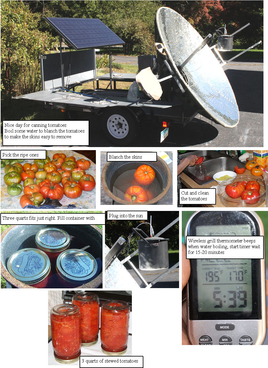 | | | Making some canned tomatoes |
That time of year again, and it is a nice day, so best do some canned tomatoes with the new trailer.
Works like a charm. Made 6 quarts, and could probably do 12 in a full day, with zero carbon.
(Posted 9/21/2013 by mikey) |
Sue Dabrowski (my better half) makes some solar eggs | 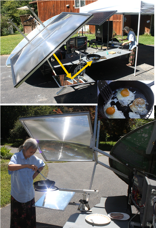 | | | Breakfast cooked with the sun. |
Trying to cook in the hibachi is tricky as it is so high in the air, so that is best used for longer unattended cooking like an oven. The large Fresnel lens is also tricky as it is above the receiver, and has so much light that it blinds the cook. I made a large mirror mount, and frying pan support, that lets one use the frying pan in a much more natural height, since the solar input is at the bottom of the pan.
Sue made us breakfast and reports that it is almost like cooking on the stove.
(Posted 8/12/2013 by mikey) |
Better solar absorber plate | 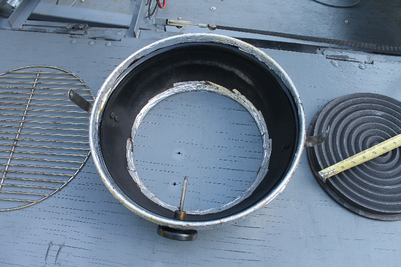 | | | Better solar reciever gives higher temperatures |
I machined some concentric grooves in the graphite to better absorb the solar energy and reduce reflective losses
(Posted 8/12/2013 by mikey) |
Insulated hibachi reaches baking temperatures | 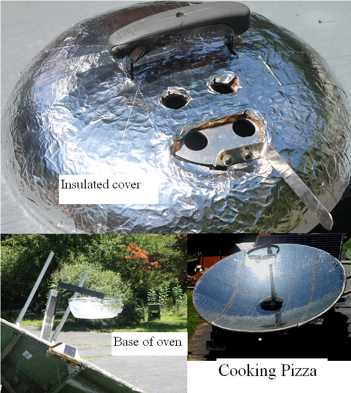 | | | better oven |
Did some changes to the solar hibachi so it can achieve higher temperatures.I added 1/2" of high temperature felt insulation to the outside of the oven, and have seen over 600F. Of course I can lower this to any temp by Defocusing the reciever graphite disk.
(Posted 8/12/2013 by mikey) |
Solarfest 2013 | 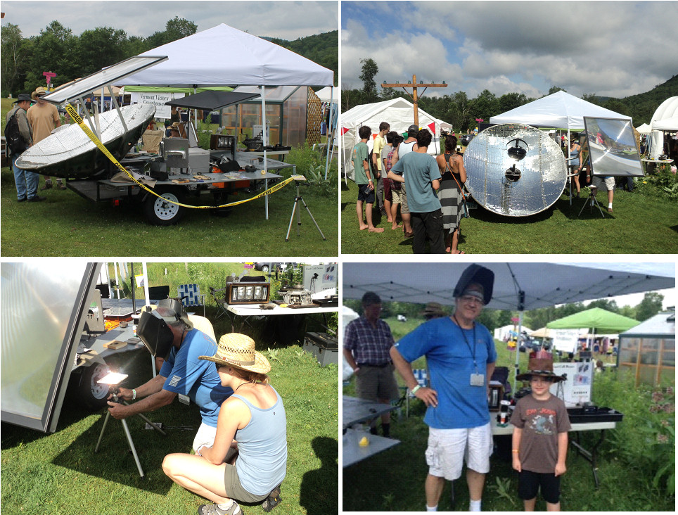 | | | Some Fun In the Sun at Solarfest |
Got an invitation to the minimaker faire at Solarfest in VT this year, so I got the trailer to the point where it was useable. I added two outriggers for the small 12" and large 12 sq foot Fresnel lenses.
The 180 mile trip where I pulled it with my Prius was interesting, I normally get 47-55 MPG, the MPG dropped to ~ 23MPG.
The event was on Sunday, and the sun cooperated for most of the day, so we got to try and cook a Pizza, and melted a lot of rocks to glass.Since Solarfest is a family event, lots of young future scientist attended
People were very interested in seeing a rock that they picked up off the ground, turn into a shiny black blob of glass.
Lots of ideas as to what to do to finish the concept, and we will blog about them here as they get finished.
(Posted 8/3/2013 by mikey) |
New tracking amplifier | 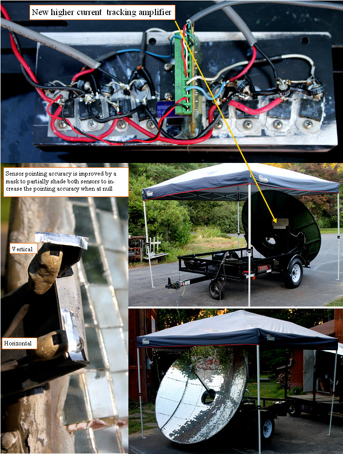 | | | Trailer tracker is working |
Went to do the first smoke test of the tracking system after I put it back together, and the magic smoke came out with a bang. Two of the power transistors blew their cases, so what to do.
I pulled out and connected one of the small IC trackers, and after one try it went bang also.
The problem seems to be the back emf on the trailer wheel, as the tracker reverses direction when at the null point, the transistors can take a good surge of current. I made a dual full bridge from 10A power darlingtons and drove it with the IC tracker board. Works well, and the heat sink hardly gets warm.
I found that we needed better pointing accuracy so I made two shade mask to partially shade the sun sensors so even the slightest angle will cause the signal to be large enough to run the tracking wheel.
Next for the grill mount and first cooking trial.
Will look into a better power amp for that axis.
(Posted 7/12/2012 by mikey) |
Vertical and horizontal trackers installed, drive wheel controls | 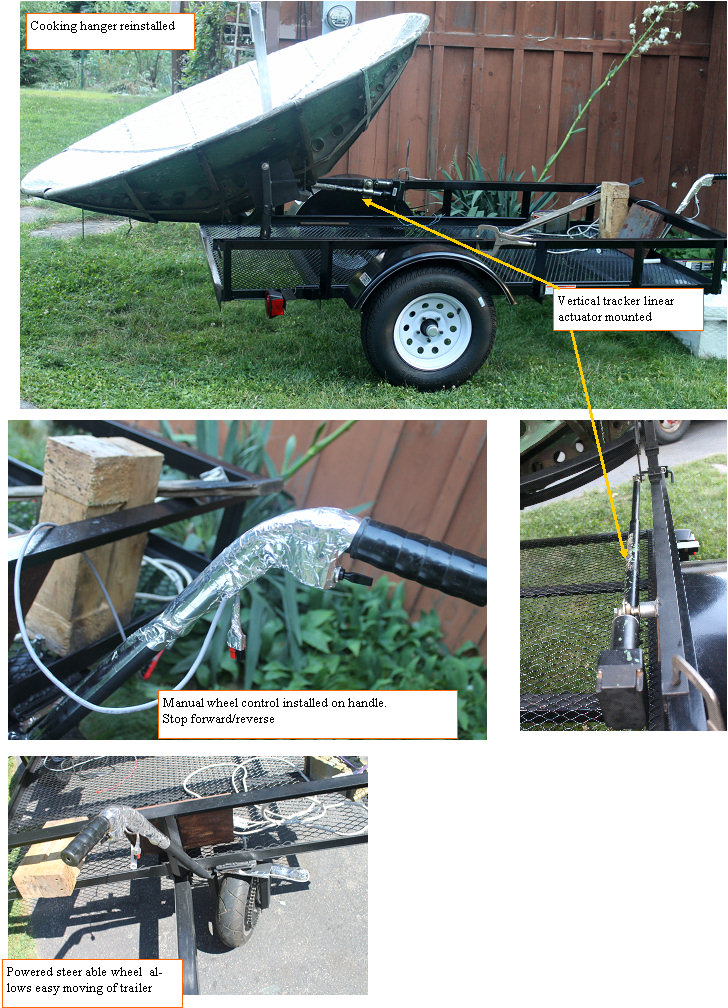 | | | Vertical, horizontal and focus axis are operating |
Moving right along.
4 days left to the party.
Got the vertical tracker linear actuator mounted and tested. also got the cooking hanger re mounted as the whole dish had to be rotated 90 degrees in order to put the removable side sections where removing them will keep the dish within the trailer width.
Drove the trailer with me in it around the yard through the grass. the tiny motor did ok, but the gear box sounds tell me that the best life will be realized if the trailer is set up on pavement, and on flat ground, but it can work on grass if required.
Also need to make sure the dish is pointing in a safe direction when parked, almost started the side of my basement entryway on fire by parking it the wrong way last night.
(Posted 7/10/2012 by mikey) |
Solar cooker gets some wheels | 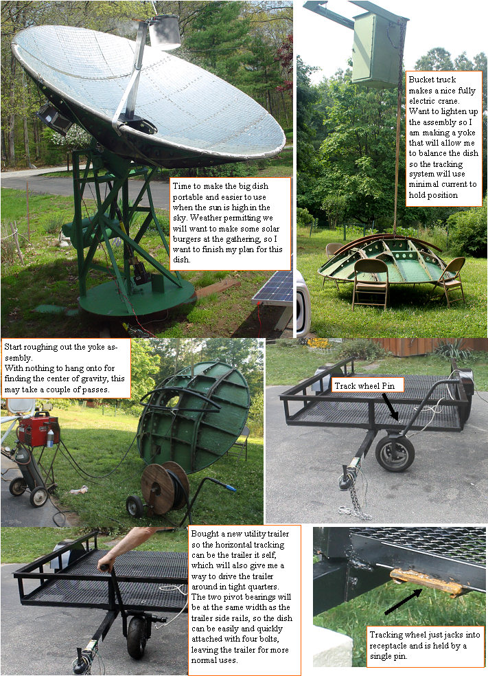 | | | The big dish gets some wheels |
Wat to make a portable Alt energy system that demonstrates the many ways that the sun can be used as an energy source. Hope to have it at the Garlic and Arts festival on Sep 29-30, so I need to get moving on it.
The problem with the dish was that it was not movable, and is pretty high of the ground, so when the sun is high, you need a stepladder to cook.
I have made several small solar trackers that use a right angle driven wheel on a 3 wheel platform as a horizontal tracker, and have been wanting to try out a full sized version. Last year I built the motorized wheel,but had not progressed much since then. (grid Charger) so I needed a break from all the software and computer stuff I have been doing, so took July 3 - 4 to get moving on this.
Bought a 5X8' trailer from Tractor supply, and proceeded to hack off the rear gate hinges.
Disassembled the old dish mount, and used the electric bucket truck like a crane. I want to get the weight to a minimum, so a balanced vertical tracking load without the huge counterweight is where I want to go.
Started by digging out some rolled square tubing I had from another project, and plasma cutting the old pivot attachment angle plates off the thing so they could be reused.
The curved tubes will bring the dish pivot point to the actual CG, and since we will likely be hanging different weight things from the dish focal point, I will provide a way to adjust the CG to easily rebalance as required.
(Posted 7/5/2012 by mikey) |
keeping the head cool | 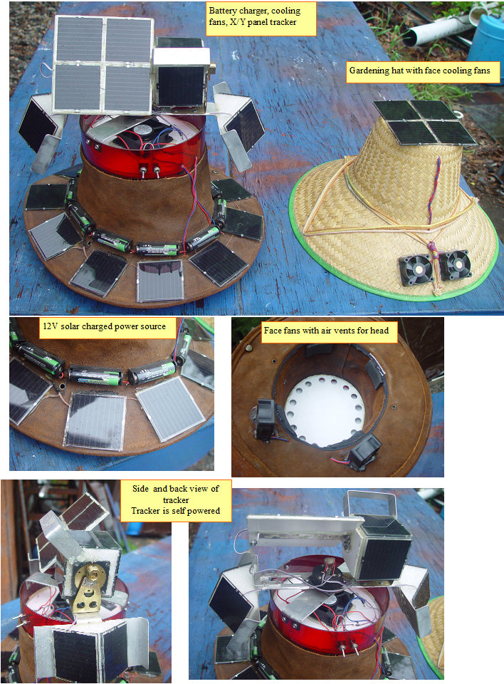 | | | keeping cool in the sun |
When working in the garden, it can get pretty hot, so I made the wife a solar face cooler that runs 2 small CPU fans. Works well in full sun, and is very light weight.
Not being the type that is easily satisfied, I got a bit carried away with my mega solar hat. The panel on top has a self powered X/Y tracker, with slip ring power output, and also has a hatband made from rechargeable NIMH cells set up as a 12V string. The panels around the brim are two parallel strings, so no mater which way you are facing the cells can charge. A bit on the top heavy side for every day use, but it is a great way to get people to come over to our alt energy displays at green events.
(Posted 5/24/2011 by mikey) |
Old Rear projection TV lens makes solar furnace | 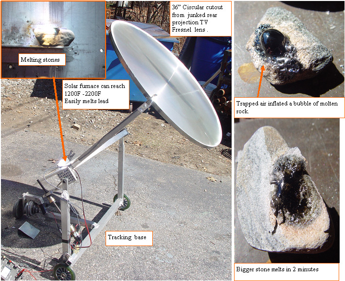 | | | Melting rock with a 36" fresnell lens |
The local transfer station always has some old TVs.
I took some tools with me and stripped off the fresnell lens from a big rear projection set that had been sitting for a couple of weeks.
The corner was cracked, so I cut out the central portion and used some silicone to glue it into a steel mounting ring.
I mounted it to a tracking base, and did some experiments.
Wow this baby can generate some pretty high temperatures.
I started by melting a 3/8" hole clear through a 1/4" thick piece of lead in less than a minute.
Then I grabbed some stones and proceeded to turn them into lava. One must have had some stored gasses, so the molten rock made a beautiful glass bubble. Wonder what else I can do with this?
(Posted 3/29/2011 by mikey) |
California or bust! Solar modified mobility scooter | 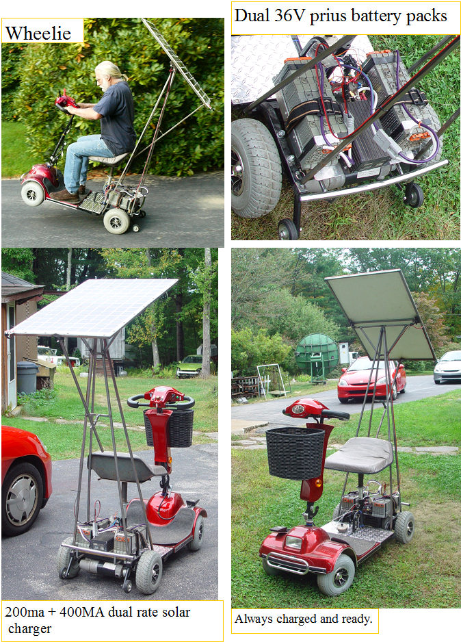 | | | California or bust |
I was at the town transfer station last week, and a guy had this scooter in his pickup truck and was going to throw it away. I kindly explained to him that this really belonged at my place, so I could replace the bum controller and batteries with something else.
I cannibalized my electric trike and took off the 36V controller, and made up a couple of 36V NIMH battery packs. The custom solar panel can put out 60VDC OC, and can charge@ 200MA or 600ma CC.
The original controller and batteries were 24V, so as expected, the thing is so fast it is fun/dangerous, and can go faster than I can run, and it does wheelies. Another story of saving an EV from the crusher, and another cool solar toy for my collection.
Not in a hurry? In theory one could make it to california using no gas.
(Posted 10/19/2010 by mikey) |
Solar cookout in 20 degree weather | 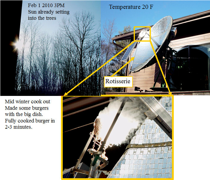 | | | A solar cookout in Feburary |
It was the end of a cold but clear day, Feb 1st and after playing with some batteries for most of the day, it was time to eat. I set up the rotisserie and cooked some burgers. They were fully cooked in only a few minutes. It seems that even with sunlight filtered by trees and the late winter sky, the thing will cook a burger as fast as a microwave.
(Posted 2/3/2010 by mikey) |
The 7 foot circle of sunlight moves to rear deck. | 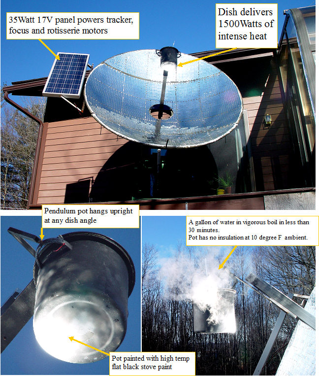 | | | Solar cooker in new position |
I had a great time cooking with the big dish last summer.
I am not ready to sit out the winter without making some progress with my solar experiments.
As we head for January 2010, I decided it was time to start using the big dish on a daily basis, and to refine it so it has many uses.
The rear deck was built with 2X6 lumber so there should be no issues with ruggedness.
I used my electric telephone truck to move the dish from the front yard to the rear deck. The bucket on the truck has a remote control pod, so I was able to move and position the dish my self.
The controls and power PV panel were moved around to deal with the partial shade that the dish will see in the morning.
Not a fun job when it is 10 degrees with a 15 MPH wind.
A switch was added to that automatically rotates the dish to a convenient food loading/unloading position, and a battery connector that will allow 2 prius subpacks to power the system, and charge from the solar panel between moves.
I put my canning pot with about 4 quarts of water right from the tap on the holder, and started the test. The sun was behind slight haze, as I said earlier, it was 10 degrees with wind, and the thin walled steel pot was not insulated at all. Within 30 minutes the pot was boiling over. All with a 7 foot circle of sunlight.
(Posted 12/30/2009 by mikey) |
Wood burning art ? | 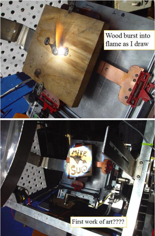 | | | Solar Art??? |
Now that the device is fully operational,it was time to see how it worked. The X-Y stage response was very quick, so I added some capacitors to the joystick potentiometers to slow down and smooth the motion.
The focal spot is a bit large for the small piece of wood that the stage can handle, but it is still possible to write and do some simple graphics.
Solar art???? Looks like I need to do some practicing, and make the thing accept multiple lenses, so I can draw with a finer spot.
Lots of fun, and a good demonstration of the servo amplifier. Amazing how much energy there is in a 1 foot circle of sunlight!
(Posted 11/9/2009 by mikey) |
Solar powered wood burner focus and lens assembly | 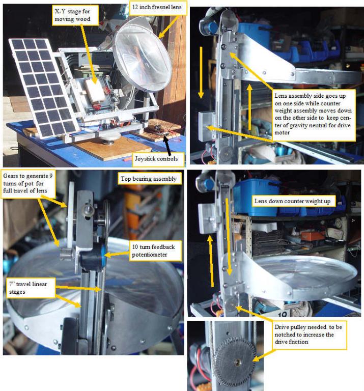 | | | focus assembly details |
I had purchased a 12" fresnel lens from Edmund Scientific about 30 years ago, for a tracking solar furnace that ran a small steam engine.
solar steam engine 1972
The old tracker had been stuffed in the attic and forgotten, so I decided that this lens was to be the biggest lens for the system. I fabricated an aluminum lens holder and used silicone caulk to hold the lens. The lens would need to be quickly focused up and down in order to draw with the assembly, but the 1.5 lb lens lifting against gravity proved to be a bit much for the motor to do quickly, and the current required to lift it was nearly at the limit for the servo amp and solar power source. Another issue was that the well balanced multitracker vertical axis would only remain balanced at one position in its 7" of travel, which made the vertical axis also draw a lot of current as the lens moved away from that balance point. I solved both issues by mounting a second linear stage on the other side of the lens mount arm. A steel block that weighed the same 1.5 lbs as the lens was mounted to this stage, and is driven by the other side of the drive cable, so as the lens moves out the weight moves in by the same amount. This configuration balanced the lens weight with the steel weight at any pointing angle from horizontal to straight up, so the drive motor only has to provide the motive force, and not have to lift any weight. The vertical axis of the tracker was able to be balanced with a fixed counter weight on the stage side. This keeps the vertical axis balanced no matter where you focus the lens.
(Posted 11/9/2009 by mikey) |
Solar powered wood burner X-Y stage | 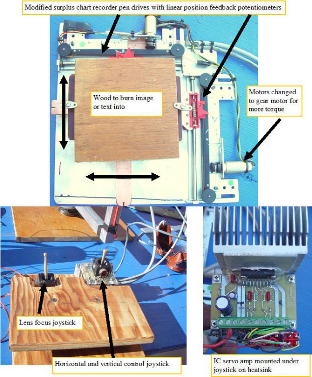 | | | X-Y servo stage |
Now that I have the multitracker operational, I decided that it would be fun to use the new servo board in a different way to demonstrate how the same board that tracks the sun can also operate an X-Y servo stage. The servo amp when used in this way, requires a position command voltage,and position feedback voltage.
I dug through my extensive stuff pile, and found some chart recorder mechanisms that I had purchased at the MIT swap meet several years ago. The assemblies have a cable drive system that moves the pen holder, with a 1K linear position feedback pot. I was going to move a stage with a block of wood so the direct drive motors would not have enough torque to do the job, so I mounted gear motors to the assembly to generate sufficient torque to lift the stage.I mounted two pieces of G10 copper clad circuit board material to both pen holders as the actuator arms. A phenolic block with a notch in the rear for the two control arms became the moving stage that the block would be mounted to.
The command pot in my device is a joystick, but any pot will work.
The position feedback pot needs to raise its output voltage when the command voltage raises or the servo will shoot off to one end or the other, and stall the motor. Not a good thing, so make sure that the stage moves the right way and stops when it gets in sync with the joystick if it does not sync, reverse the motor leads so it goes the other way, and you should be good to go.
(Posted 11/9/2009 by mikey) |
multytracker 1 | 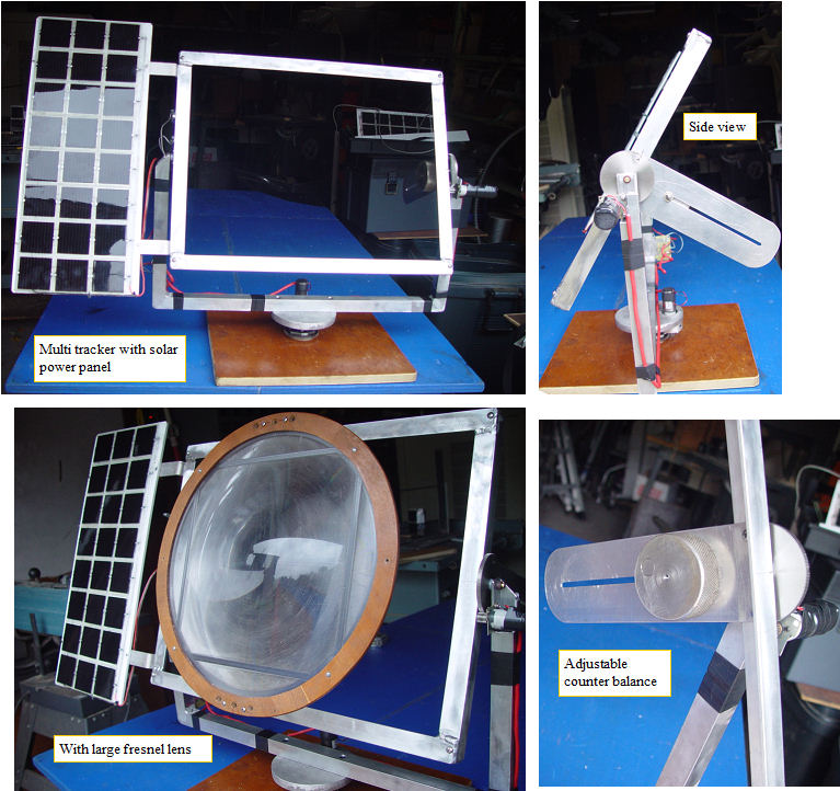 | | | multy tracker 1 |
The tracker works very well, and quickly find and will point at the sun.
Some devices I hope to mount on the tracker
1. 250 v solar panel(for charging the Insight HV pack.
2. Solar wood burning drawing device.
3. heliostat
(Posted 10/9/2009 by mikey) |
Multy purpose tracker 1 | 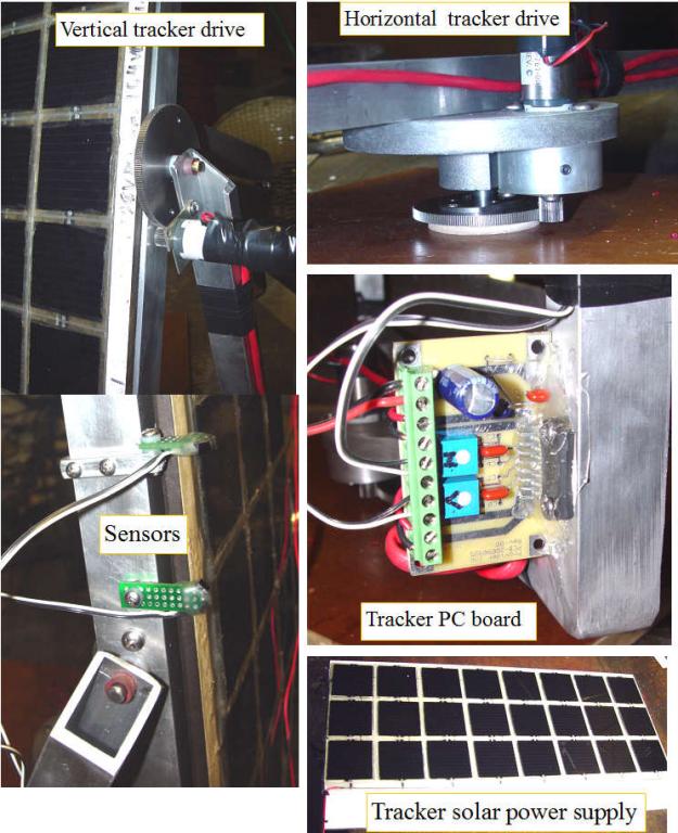 | | | IC tracker 1 |
I had to put one of the new boards to the test, so I built a rugged tracker that can have several devices mounted to it.
The base is a piece of plywood, and the horizontal drive is a gearmotor driving a large spur gear.
The spur gear is attached to the base, so the gearmotor rotates with the upper assembly by riding around the large fixed spur gear.
This system allows a strong bearing on the main horizontal axis, and does not expect the motor shaft to carry the assembly, it only drives it.
The vertical drive is built the same way, and is a large aluminum angle frame that the devices to track will attach to.
The sensor PC boards are mounted to the side of the frame, and can be easily adjusted if necessary.
The amplifier has lots of gain, so we must adjust the gains so the tracker accurately follows the sun, but not so much that it begins to mechanically oscilate.
I built up a custom solar panel that can output 650MA @ ~10-12VDC, which should easily power the well balanced device.
(Posted 10/8/2009 by mikey) |
Designing a simpler and lower cost solar tracking amplifier | 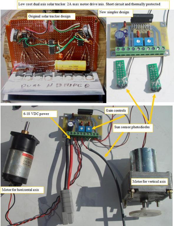 | | | New low cost dual solar tracker |
I have been using a dual H bridge solar tracker design for many years, but it has a lot of parts, is relatively cheap, but takes some time to build on a breadboard. I needed to make another tracker for a new small solar dish, and decided to take a new look at the circuit.
After some research I found a nice solution.
Since a single power supply is how I wanted to power the system, a full bridge servo amplifier which can source or sink current through the motor in either direction was a requirement. I found that a bridge tied load audio amplifier chip if dc connected rather than the ac coupling that it was designed for will do the job nicely.I built a prototype on a breadboard, and found that it worked as well as the much more complex and expensive discrete component version that I have been building, and only has a few support components, so it is both inexpensive and easy to build.
a schematic of the circuit:
IC dual solar tracker
After some further tweaking of the design, I will be offering the built and ready to use dual tracker system including the photo diode solar sensors as a product.
Buddy Paul Provost laid out the pc board so that the circuit could also be used as the 15W stereo amplifier that it was designed for by simply cutting two etches and adding some capacitors.
The circuit can also be used as a dual position feedback servo by using a feedback potentiometer geared to the motor output on the +input and a position command potentiometer on the - input.
The motor will turn and rotate the feedback potentiometer to the position commanded by the command potentiometer. The command can also be generated by a computer with a PWM or analog output.
The board is designed with the chip on one edge, so the chip can be attached to a heatsink or chassis. My first test with 1-2A draw showed minimal heating of the chip, so only a minimal heatsink is required unless the system is pushed to the 2A limit frequently.
As with any tracking system, mechanical design can make or break the system. The axis should have balanced loads so the servo does not need to continuously drive current into an axis just to hold position.
(Posted 10/7/2009 by mikey) |
No more throw away batteries please | 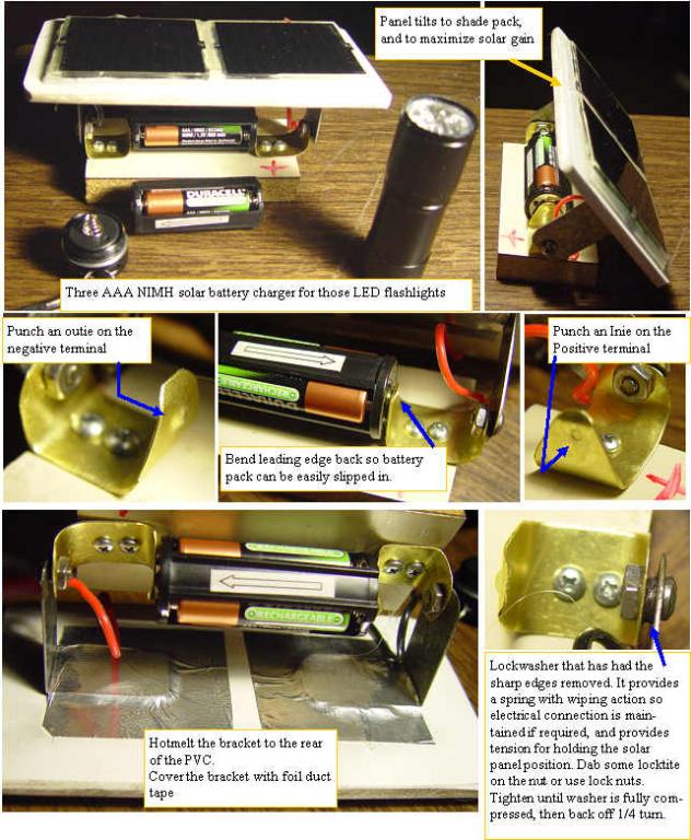 | | | Solar three NIMH cell charger |
I needed a flashlight, and like so many people, I bought some of those cool LED flashlights. I grabbed one out of my drawer, and the three AAA batteries were dead. I went to buy some AAA alkaline batteries and was shocked when I saw the price. I saw 4 NIMH rechargeable AAA's with a charger,that can be used 500 times and bought that instead.
The cost of ownership of a well maintained rechargeable NIMH AAA is many times less than the throwaway kind, and it reduces the amount of energy required to make the one use batteries and to dispose of the spent ones.
The only thing I did not like about the NIMH was the wall wart charger that will inevitably be forgotten and stay plugged in between the charges, so it becomes part of the background load of the electrical grid.My charger and millions more are just wasting valuable energy.
I looked at my cute 3.2V 85MA solar cells, and decided that a solar charger makes much more sense. The flashlights will run for quite a few hours on a full charge. The 800 MAH duracell NIMH cells can take the 40-85 MA from the panels for many hours and only get slightly warm,and they will be topped off and ready to use when you need it.
A piece of PVC sign board, some hotmelt, A diode for isolation, and some strips of brass and steel, and you have a solar NIMH charger for the three cell battery packs that are used in many of the flashlights. One pack is used while the other sits in a sunny window getting charged with the greenest energy we will ever have.The two panels are put in series with the diode, and the positive and negative solar leads are soldered right to the brass terminals.
No regulator should be required at the
C/10-C/20 rate that the panels max out at.That is only 1/2 watt, which the pack can easily dissipate. I will do some long term test to see how the cells hold up to a several day charge which will hold them at the full charge point.
(Posted 10/15/2008 by mikey) |
More improvements to the dish | 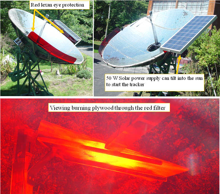 | | | further improvements |
Had a couple of batches of tomatoes to can, so while waiting for the water to boil, I welded up a solar panel mount, so the solar panel can be attached to the dish permanently. Since the simple servo is not smart enough to find the sun each morning, I can just rotate the solar panel so it gets power, and then get the tracker in the approximate direction for normal tracking and then it is good for the day.
I have been wearing dark sun glasses when using the dish,as the sun at the focus point is too bright to look at with unprotected eyes. I found a sheet of red LED filter lexan in my stock pile, so I made up two viewing filters, so the glasses are not required.
(Posted 9/19/2008 by mikey) |
canning season is here again | 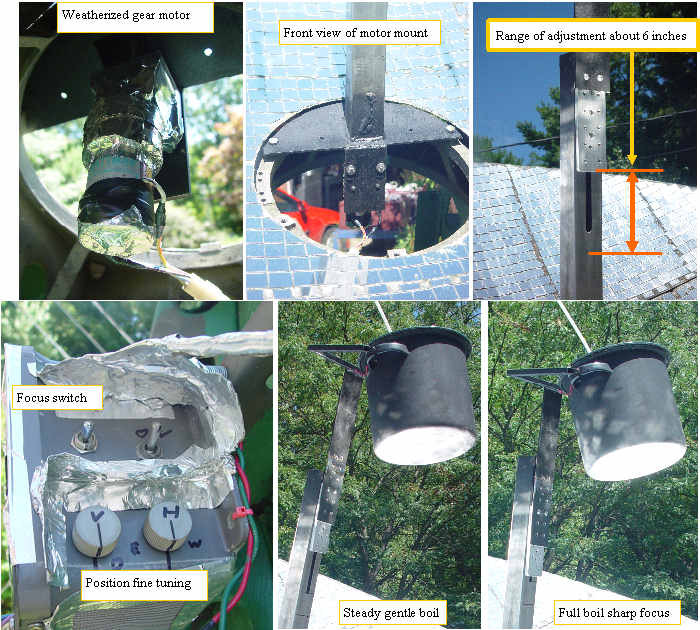 | | | Dish third axis, FOCUS |
Sue picked a huge crop of cucumbers, and wanted to make some pickles.
We did the first batch of 7 quarts on the electric stove. The canning pot took a full hour to reach boiling, then 5 minutes at boil for a total of nearly 2KWh to preserve them.
I prepared the dish for canning so the subsequent batches could be processed by the sun, but did not want to deal with the fabric thermostat, so I added a focus adjuster. The focus system has to be strong enough to raise the heavy pot of jars and water, and my rule that I must be powered with the same 50W solar panel required some digging in my surplus motor box. I found a Pitman 19.5:1 gear ratio 24v motor, that did the job with power to spare. The lead screw was a surplus acme threaded rod with a single ball bearing on the bottom end, and a bronze acme nut at the top.
The parts were surplus from the polyscan bone density/thyroid scanner that I designed and built back in the 80's.
I got 6 inches of travel out of the focus, and made a new mount for the pot hanger to put the pot bottom just at the sharpest focus when at the bottom of travel. Once the pot starts to boil over, I adjust the focus by raising the pot reducing the solar energy. I was able to maintain a gentle boil without boiling over.
In theory this could be automated to maintain a fixed temperature. I processed 9 quarts of pickles this morning. Yummy and with no guilt as far as carbon production.
(Posted 8/26/2008 by mikey) |
Burgers are better | 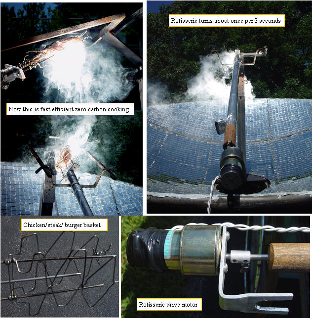 | | | WOW is this thing a fast cooker |
Since I am not much of a fan of hot dogs,and I was getting hungry, I decided it was time to try some burgers. I added a 1/4" shaft off the bottom of the broom handle, with a small gear motor to turn it, I made a small bracket for the dish bottom,for the drive motor to sit in.I powered this motor with a second small solar panel, and have included an on off switch.
A top rotating bracket that fits the adjustable fork, and made a stainless steel wire basket for both sides of the forks.The rotisserie turns at about 30 RPM
WOW, I never saw a burger cook so fast. It was evenly cooked right through in just about 1 minute, with no burning. The center temp got to 150F. I like my burgers a bit more rare, so next time I will make them thicker, and cook only to 120F or so. No grill warm up time, zero carbon production during cooking, and a fully cooked burger in about a minute. Why are we using charcoal and gas????
The same basket and rotisserie should do steaks and chicken, so that will be my next test.It is so much fun cooking with the sun.
(Posted 8/21/2008 by mikey) |
Cooking some hotdogs | 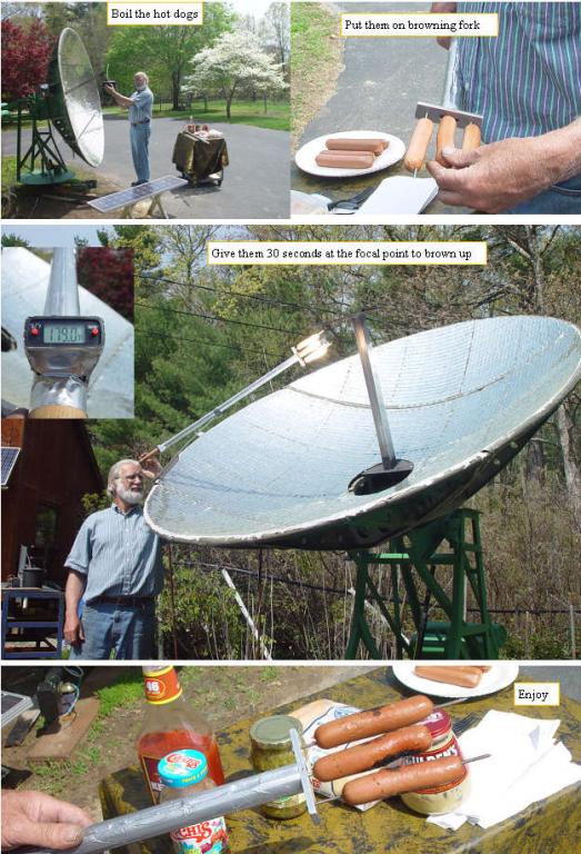 | | | solar hotdogs |
Ok canning season is in the fall, and here we are mid summer, and we are using charcoal and propane to have some cookouts. I decided it was time to start using the big dish for some green cookouts.
I boiled the dogs first to cook them thoroughly, then I brown them in the intense heat before eating. It only takes 10-20 seconds to brown the dogs. Next,steaks and hamburgs.
(Posted 7/14/2008 by mikey) |
All weather dish movers | 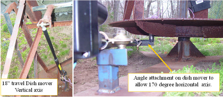 | | | New drive actuators for dish |
Taking a break from the bucket truck, I finally got the two 18" dish movers mounted on the big Solar furnace.
The vertical axis was easy, I used the old actuator arm on top, and welded up a simple bracket on the bottom.
The actuators have adjustable stops, which I adjusted so the travel was full range without hitting the stops. The horizontal axis was a bit more work, as the VW wheel, and stiffening webs only gave a narrow path for the actuator shaft to pass by. I wanted as near to 180 degrees of rotation as possible, so an offset bracket was made for the dish side so the actuator would clear the mounting shaft. It is a bit heavily loaded when at the two extremes of travel,because of steep actuation angle, but is smooth and strong every where else.Next the water proof box for the electronics.
(Posted 4/27/2008 by mikey) |
solar cell adhesion test #1 | 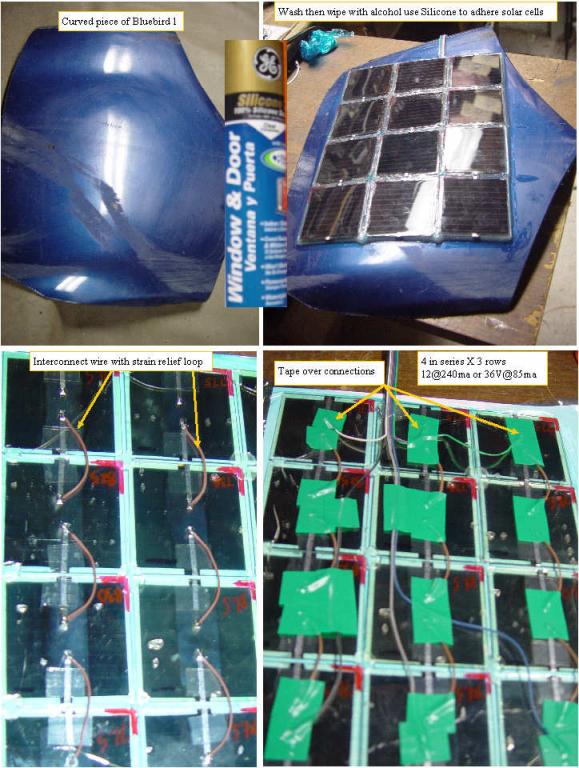 | | | silicone adhesion test |
I grabbed a piece of the smashed front end of Bluebird 1, washed it with soap and water, then wiped it off with alcohol. I prepared the 4X3 array (4 in series X 3 strings)by laying them carefully on a piece of plastic. I tacked the corners with a dab of hot melt. Soldered the series jumpers with a small strain relief loop on each. taped over the soldered connections, and tacked down the ribbon output cable.
I will let this dry for a week before testing.
(Posted 2/26/2008 by mikey) |
Solar cells on my Insight ???? | 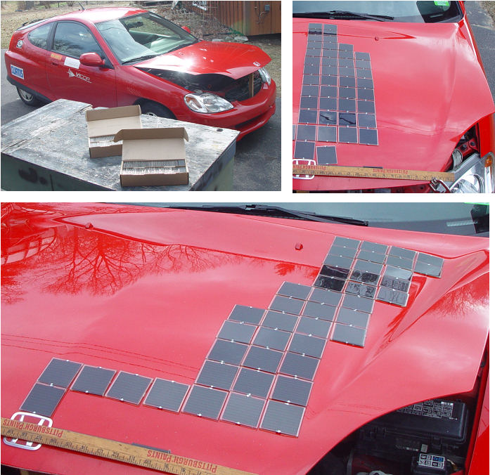 | | | 213 cells or 17.75 Watts on hood |
Ok here it is, the moment of decision that we all must face when trying to make progress.Do I ever expect this car to be brought back to stock condition again? Naaaa!
The 250 V (open circuit)panel that I built outputs 85ma of current at 180V with 56 of the mini solar panels.
The next step along the path is the integration of solar cells into the body of the Insight. The only way to put glass cells on a car body is to shock mount them so they can take some flex, and make damn sure that they will not blow off.The small 2.4" size of the mini panels allows them to somewhat follow the contour of the hood and roof.
The hood will hold 213 cells and output 17.75 watts.
The IMA pack can handle 250ma without damage. 56 cells will yield a solid 85ma at 180VDC.
3 parallel strings will yield 255ma so the hood alone
can take care of trickle charging the IMA battery.
The roof test will need to wait for a warmer day.
Aerodynamic pressures when traveling at 100 MPH can be very strong, and the cells had better not fly off.
Some interesting problems to solve, hopefully in a way that will not involve damage to the car????
Suggestions?
(Posted 2/20/2008 by mikey) |
Solar teaching toys | 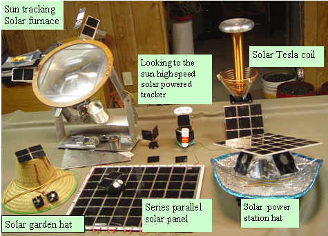 | | | Solar teaching toys |
I have been invited to do a solar workshop at a local high school, so I have assembled and built several interesting solar powered devices.
The Solar Tesla coil is not finished yet.
More fun in the sun.
(Posted 1/8/2008 by mikey) |
Tracking the sun Big Time | 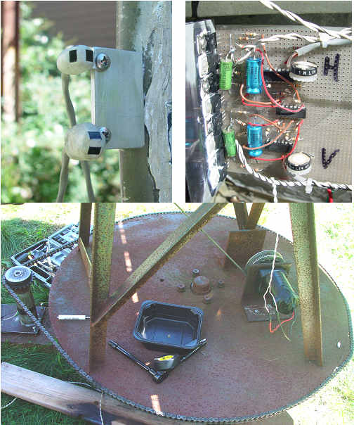 | | | Tracker Version 1 |
The big hurdle that many people have when thinking of converting your old big dish into a solar furnace, is how to make it follow the sun.
First thing you need is a base, I welded up a triangulad base from heavy channel. The front wheel bearing from a VW bettle was attached to a large 1/4" steel disk.
Once the disk was mounted to the wheel hub, the disk was rotated and a line drawn at the largest continuous circle that would fit.The steel was trimmed to the line, with hand jigsaw, and finished with hand grinder.
I wanted a chain drive, so I turned the big disc into a giant sprocket in a crude but effective way.
I took a #40 chain, and wrapped it around the big disc. I used a center punch and marked the disc edge each 10 teetk of the chain.
Uf course, it did not come out an even number of teeth, so I made a single tooth add on to the disc to exactly keep the chain in place simulating the correct diameter so the teeth exactly match around the diameter. I drilled and tapped a 10/32 hole at each punch mark, locktited a 10/32 threaded rod into each, and cut off the lengths and deburred and shapped the teeth and it worked beautify.
Tracking is really pretty simple,especially if it is kept in the analog world. Never underestimate the lowly Op amp, and a few power transistors in a full bridge servo amp.
The sensor is something I invented 20 years ago, that is the magic in the self powered solar tracker below.
Two photo sensors are configured so the two detector outputs will cancel to zero V when both have equal angle/illumination from the sun.
Photo diodes or chips of solar cells work well as photo detectors. I set them at 45 degrees to each side of where I want the null to be. The ones I used on the big dish are set in epoxy putty.
The first drive system has the horizontal axis powered by a precision harmonic drive gear motor that is way too expensive for a dish,but was in my surplus motor box.The vertical axis with just a simple wench, is very balance sensitive.Any imbalance against gravity has to be constantly provided by the motor to hold a position. Weather protection for a chain is too difficult.
I found some nice C band big dish satellite movers for $39, and they are waterproof and since they are an acme screw drive, do not need to provide much holding force even with a big weight imbalance.
The new motors will be put on the system in the spring.
A schematic of the basic tracker is available on the downloads page:Simple Tracker schematic
The photo detectors I used were osram BPW34FA which are available from digikey
photo sensors
(Posted 11/1/2007 by mikey) |
Solar tracking with no electronics" Solar Puppet" | 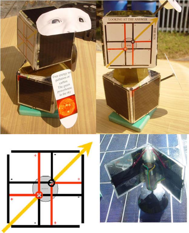 | | | Solar powered solar tracker no electronics |
Many years ago I built a small device that follows the sun without any electronics. With my new found solar panels and some nice precision gear motors I built a cute completely solar powered devise that looks to the best source of green energy we will ever have, the sun. The baby's eyes look at it's generations best hope for a kind world.
The dual cubes are set up so that the opposing solar panels current cancels when they both are evenly illuminated by the sun.The resultant voltage is zero. When the sun moves to the west, the panel on the west side gets more direct sun, and the east side gets less sun.The increased current on the west side brings the voltage across the cells up with the polarity of the west panel. This drives the motor to the west until a new null is located. The vertical axis works the same.
The shades amplify this unbalancing effect near the null point for more accurate tracking.
When you bend over to read the sign, your shadow makes the device look away. When you move again so it gets full sun, it leaps back quickly to point directly to the sun. Almost seems alive. A cool toy and science project.
The two solar panels on the back assure 360 degree recovery. A simpler dual panel tracker works just fine except for when the sun is behind both panels.
I discovered another cool use for the device. A solar puppet. I stand at a distance, and using my hand/fingers to cause a shadow on either the horizontal or vertical cells, I can make the device shake up and down for a yes, and left to right for a no.
Is solar energy our best source of green energy? I shade the vertical cells to make the eyes go up and down for a "YES". Do we have a lot of time to switch to alt energy sources? A shading of the horizontal cells makes the eyes move left and right to say "NO"
The things to be aware of if you want to try to build your own version.
The low voltage gear motor with the ideal gearing is not something you can buy easily or cheaply.
The quickness of the movement and the accuracy of tracking, heavily depend on the balance of power available from the cells, and the gear motor characteristics I was lucky to find the ideal motors at a swap meet, and have not found gear motors that work as well again.
I have some cheap non geared motors that respond sluggishly, and do not track very accurately, but demonstrate the principal.
I have some very high quality gear motors that are very positive in their response, and do track accurately, but do not move very fast, so you don't get the alive like response that I get with the motors on the puppet.
Some day I will put up a video that explains all of this and shows the difference that the choice of motors brings.
The motors I used that work so well,if purchased new would cost over $100 each, taking this out of the cheap solar demonstrator category.
The ideal motor is low voltage (will run with 1V)has a 4-6:1 gear ratio, and requires very low current(<10mA) to start and operate
(Posted 9/26/2007 by mikey) |
Second test | 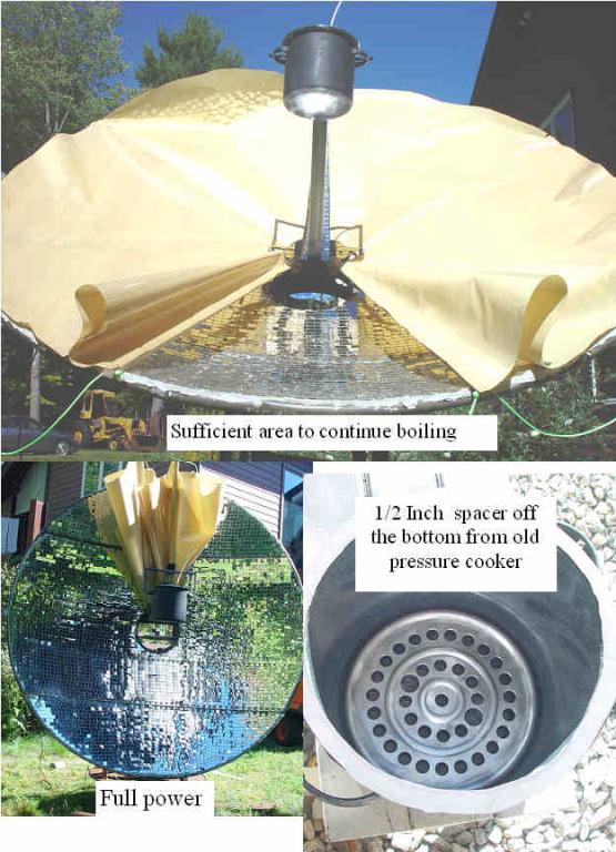 | | | Testing and Tweaking |
Sue got three more quart jars of tomatoes ready, and I ran my first test with thermostat.
I still had the top blow off problem, where internal steam was generated and the caps were loosened. I realized that the very hot surface of the pot, and the small amount of water between the jar bottoms and the pot bottom, were allowing the water directly under the jars to boil first, and therefore the jars were heating the water bath, and were reaching boiling before the rest of the pot. I had saved a circular aluminum shelf from the bottom of an old pressure cooker, and will use that next time, and believe that should solve the internal pressure issues.
I could clearly hear the blup blup of the water boiling,and to my surprise, I only needed a small part of the dish to keep it boiling.
This thing is asking for a steam pressure boiler. Bet I could get some serious pressures going.
I did some energy calculations.
I put 7 quarts of water from the tap at 60F into the pot. Seven quarts weighs 14.6 lbs. I heated the water and the pot from 60F to full boil in about 30 minutes. That temperature change of 152F took 152 BTU X the 14.6 lbs or 2219 BTU/ half hour.
1KW generates 3415 BTU/ hour, so my 4438 BTU per hour dish is putting 1.3KW into the water. That was with the folding thermostat opened but still blocking some of the dish, and the mirrors needing a cleaning.
Can't wait to see what the 10 foot dish will do.
Click for some ideas on how you can make your own
Making small solar concentrator
(Posted 9/23/2007 by mikey) |
Canning pot | 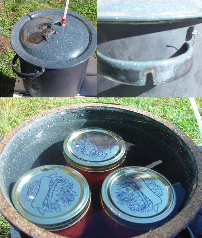 | | | The boiler |
Sue usually canned 7 quarts at a time, but I did not like the idea of suspending the weight of several gallons of boiling water in mid air on a sometimes twitchy dish. I searched all the stores, and finally found a Martha Stewart pot at Kmart that fit three quart jars perfectly, with just a bit of room. I notched the handles so the low CG would always keep the pot upright. I glued a cork gasket on the upper lip using silicone caulking (good for 450F). A vent tube and thermometer port, with two springs to hold on the cover, and I was ready to go.
(Posted 9/23/2007 by mikey) |
The sun is dropping 1KW/SQ meter | 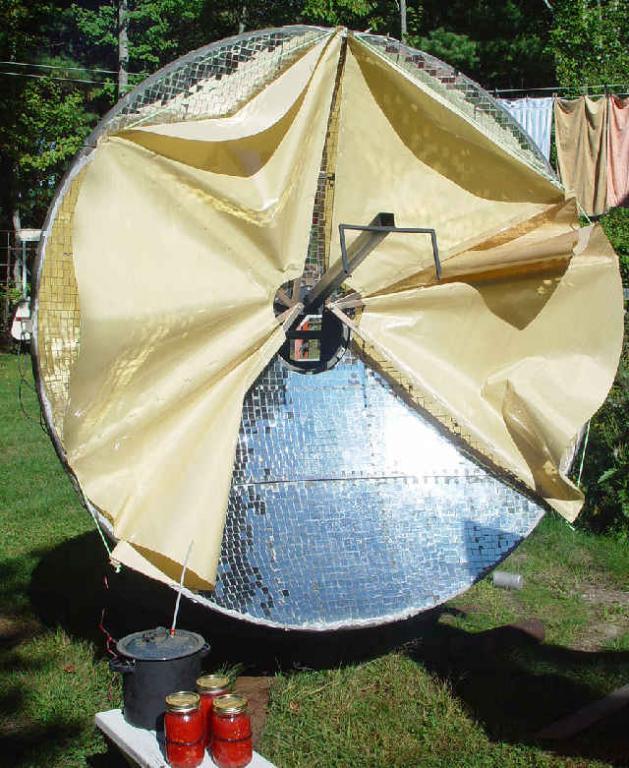 | | | Solar thermostat |
To put that into perspective, your microwave oven uses about 600-1kw when running.
I put the mirrors and built the stand for this old radar dish in the early 80's but never got the thing to do any useful energy gathering until this week.
Sue loves organically grown veggies, and has canned pickles, tomatoes, and beans for many years. When I see her heating the large canning pot to a boil and holding it there for nearly a full hour start to finish, It hurts me to think that the free veggies have sucked so many electrical watts to preserve them. I finally got a working canning system going.
The dish needed a tracking system, and a way to hold the pot so it was properly heated at any solar position.
The first run of the system showed me that I had way too much power.The cover had blown out on one of the jars, as the boiling was so intense, as to bring the tomatoes to the boiling point, and turn the internal water to steam. I needed a thermostat.
The first approach that came to mind was to move the container to a different point in the focus, but I did not want to have to play with the tracking system calibration and wanted to have the system self operating.
I thought of how oriental fans fold up and spread out, and built a rather crude and rude dual fan one for each side of the dish. The "Thermostat" is part open in photo.
(Posted 9/23/2007 by mikey) |
|


